User manual ver. 20200323
This document contains information on the safety, installation and use of the Auraton 200 RT device.
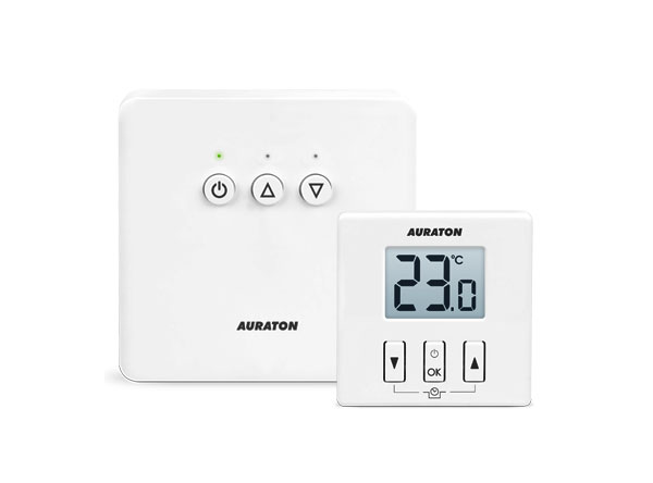
Wireless temperature controller
AURATON 200 RT temperature controller, built on the basis of advanced solutions
| U | The "FrostGuard" function protects the room from freezing. |
| & | Possibility of cyclically lowering the programmed temperature by 3°C for a period of 6 hours. |
| LCD | Illuminated LCD display The illuminated display allows you to monitor the device's operation even in poorly lit rooms. |
| 16A | of up to 16A/ 10A. Low-spark mains voltage switching technology ensures minimal wear on the relay contacts. |
Optional system components
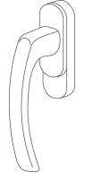
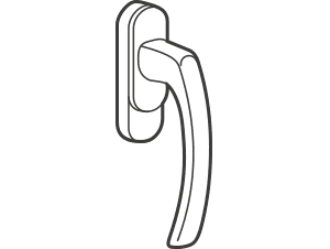
AURATON H-1
Window Handle (sold separately)
An optional element of the system is a window handle equipped with a transmitter and position sensors. This allows the installed handle to transmit information about the window's status. The handle can distinguish between four window positions: open, closed, tilted, and unsealed (microventilation). The handle sends information to the RT receiver, which decides whether to activate the relay, for example, by turning off the heating device when the window is open or lowering the temperature by 3°C when the window is tilted, thus saving energy. One RT receiver supports a maximum of 25 handles.

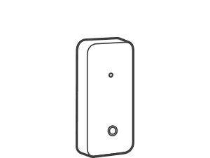
AURATON T-2
Thermometer (sold separately)
Optional element of the system, allowing you to control the temperature in a room other than the one where the AURATON 200 RT controller is located.
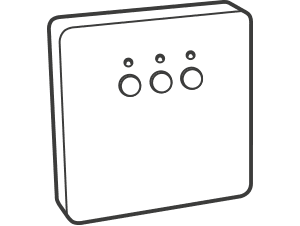
Receiver description
The AURATON RT receiver works with the AURATON 200 RT wireless controller. The receiver is mounted on the heating or air conditioning device and can operate under a 16A/10A .
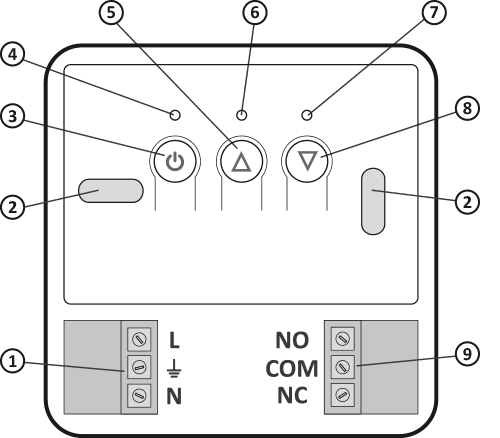
- Detachable 230V power connector terminals
- Mounting hole
- Power button
- Power LED
- Paired Device Check-out Button
- Diode indicating that the actuator is switched on
- LED indicating that the actuator is turned off
- Button for pairing the device with the RT receiver
- Detachable clamps
Legend – description of the diode signaling
| D G | The diode is green – the actuator is turned off (COM and NC contacts closed). |
| E I | The diode lights red – the actuator is switched on (COM and NO contacts closed). |
| D H | The LED flashes green – the RT receiver is waiting for the device to be paired – (chapter: "Pairing the AURATON 200 RT wireless regulator with the RT receiver"). |
| E J | The LED flashes red – the RT receiver is waiting for the previously paired device to deregister – (chapter: “Deregistering the controller from the RT receiver”). |
| K | The LED flashes alternately red and green: ALARM – the RT receiver has lost connection with one of the paired devices – (chapter: "Special situations") RESET – the RT receiver deregisters all previously paired devices – (chapter: "Deregistering all devices assigned to the RT receiver") |
| F | Green power LED – RT receiver on. |
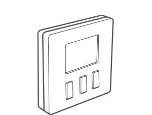
Description of the temperature controller
The front of the housing features a backlit LCD display and three function buttons.
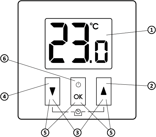
- LCD display
- Increase temperature button
- Temporary temperature reduction mode buttons
- Temperature reduction button
- Pairing buttons
- Confirmation button or controller on/off
| d |
|
Display
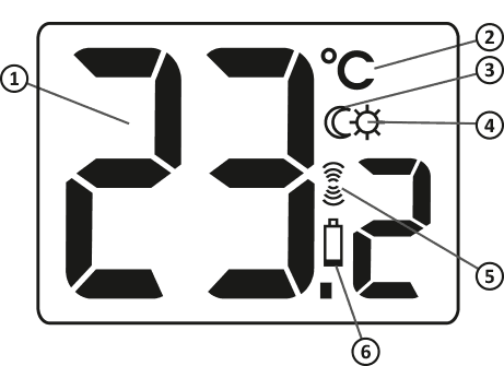
- Temperature
In normal operation mode, the controller displays the temperature of the room in which it is currently installed. - Temperature unit (
R ) Indicates whether the temperature is displayed in degrees Celsius. - “Temporary temperature reduction” mode indicator (
T ) Appears when the “temporary temperature reduction” program is running. - "Temporary temperature reduction" mode programming indicator (
S ) Indicates that the user has scheduled a "temporary temperature reduction" mode. This appears when the mode is not currently being implemented, but the "temporary temperature reduction" function is active (for more information, see the "Setting the temporary temperature reduction" mode" section). - Transmit Symbol (
W ) Indicates communication with the receiver. - Low Battery (
X ) This indicator appears when the battery voltage has exceeded the minimum allowable level. The battery must be replaced as soon as possible.
Choosing the right location for your temperature controller
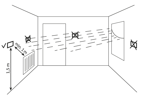
The proper operation of the thermostat is largely influenced by its location. Siting it in a location without air circulation or in direct sunlight will result in incorrect temperature control. To ensure proper operation, the thermostat should be mounted on an interior wall (partition wall). Choose a location where you spend most of your time, with free air circulation. Avoid proximity to heat-emitting devices (television, radiator, refrigerator) or locations exposed to direct sunlight. Avoid placing the thermostat directly next to a door to avoid vibration.
Battery installation/replacement
The battery compartments are located inside the controller on both sides of the display. To install the batteries, remove the controller housing as shown in the illustration.
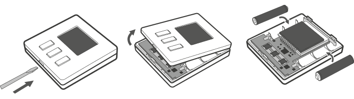
Insert two 1.5V AAA batteries into the battery compartment, paying attention to the correct polarity of the batteries.
We recommend alkaline batteries for powering AURATON controllers. Rechargeable batteries should not be used due to their low rated voltage.
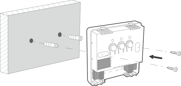
Mounting the AURATON 200 RT temperature controller to the wall
To attach the AURATON 200 RT to the wall:
- Remove the controller housing (as shown in the "Installation/Replacing the Battery" section).
- Drill two 6 mm diameter holes in the wall (mark the hole spacing using the rear part of the controller housing).
- Insert the expansion bolts into the drilled holes.
- Screw the rear part of the controller housing to the wall using the screws included in the kit.
- Install the batteries and put the regulator housing back on.
If you have a wooden wall, there is no need to use expansion bolts. Simply drill 2.7mm holes (instead of 6mm) and drive the screws directly into the wood.
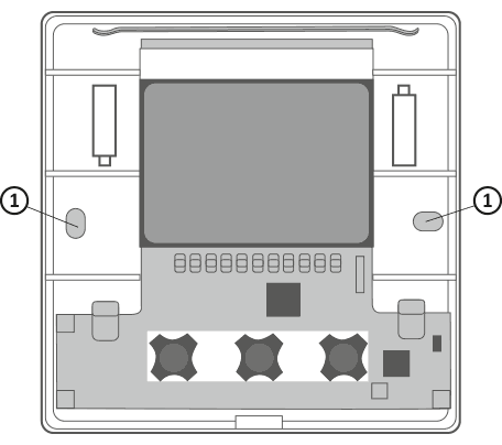
- Hole for mounting screw.
Alternative mounting methods
The controller can be attached to a smooth surface using double-sided tape, for example. The controller can also be placed anywhere on a flat surface using the stand located on the rear of the housing.
How to mount the RT receiver
Q
The cables supplied with the controller are designed to carry a maximum load of 2.5A.
If you connect devices with higher power, replace them with cables of appropriate cross-section.
The power supply should be turned off when installing the AURATON RT receiver. It is recommended that the receiver be installed by a specialist.
The building's permanent installation must include a circuit breaker and overcurrent protection.
For ease of installation, the connectors are equipped with removable terminals. These terminals can be disconnected from the controller before making cable connections. Wires can be routed from the bottom of the receiver by breaking out the holes in the mounting plug, or from the back of the receiver if the wires are led out of the wall. To connect from the back, break out the plug.
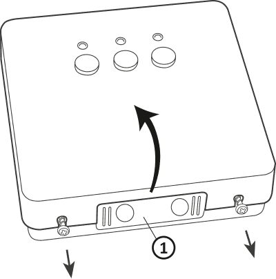
- mounting plug
Remove the front cover of the Auraton RT receiver by unscrewing the screws halfway down.
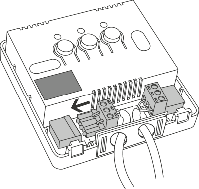
Connect the heating device to the Auraton RT receiver's control connector terminals. Follow the heating device's service manual. The most commonly used terminals are COM (common) and NO (normally open).
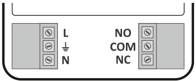
Connect the power cables to the Auraton RT receiver power connector terminals while observing safety regulations.
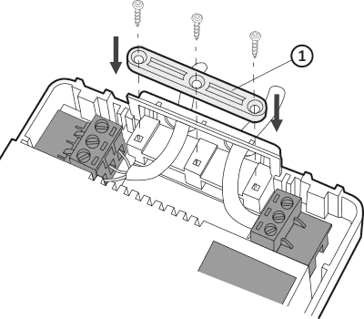
- Cable mounting bracket.
After connecting the cables, secure them with the "cable retaining clip" and re-screw the cover to the AURATON RT receiver.
Mounting the RT receiver to the wall
To attach the AURATON RT receiver to the wall:
- Remove the cover from the front of the controller (see the section "How to mount the RT receiver") .
- Mark the position of the mounting screw holes on the wall.
- In the marked places, drill holes with the diameter of the dowels included in the kit (5 mm).
- Insert expansion bolts into the drilled holes.
- Screw the RT receiver to the wall with screws so that they hold the receiver securely.
If the wall is wooden, there is no need to use expansion bolts. Drill 2.7mm holes instead of 5mm and drive the screws directly into the wood.
Do not place the RT receiver in metal housings (e.g. mounting box, metal furnace housing) to avoid interfering with the operation of the controller.
Pairing the Auraton 200 RT wireless controller with the Auraton RT receiver
After connecting to the mains, turn on the receiver by briefly pressing the power button ( F ). When the device is turned on, the green power LED will light up and you will hear a single beep. To turn off the receiver, e.g., outside the heating season, hold the power button for 3 seconds until you hear a double beep and the green power LED turns off, turning off the heating device.
The AURATON 200 RT wireless thermostat sold with the AURATON RT receiver is already paired. Devices purchased separately require pairing.
- Pairing the 200 RT controller with the RT receiver is initiated by pressing the right pairing button ( D ) on the RT receiver – a single beep – and holding it for at least 3 seconds until the LED starts flashing green (double beep), then releasing the button.
The AURATON RT receiver waits 120 seconds for pairing. After this time, it will automatically return to normal operation. - On the AURATON 200 RT controller, press the b d or c d for 6 seconds until the transmission symbol ( W ) lights up on the display.
- Successful completion of the pairing is indicated by the LED on the AURATON&RT receiver stopping flashing green, by a single sound signal and by the receiver switching to normal operation.
If an error occurs during pairing, repeat steps 1 and 2. If further errors occur, deregister all devices by RESETting the RT receiver (see "RESET – Deregistering all devices assigned to the RT receiver") and try pairing the devices again.
Only one temperature controller can be added to one receiver.
Deregistering the controller from the RT receiver
- To deregister the 200 RT controller from the RT receiver, press the left deregistration button ( E ) on the receiver for at least 3 seconds until the LED flashes red, then release the button. The sound signal works in the same way as pairing, i.e., pressing the button is signaled by a short beep, followed by a double short beep after 3 seconds.
The AURATON RT receiver waits 120 seconds for the device to be deregistered. After this time, it will automatically return to normal operation. - On the AURATON 200 RT controller, press the b d or c d for 6 seconds until the transmission symbol ( W ) lights up on the display.
- Successful completion of deregistration is indicated by the LED on the AURATON RT receiver stopping flashing red, by a single sound signal and by the receiver switching to normal operation.
If an error occurs during deregistration, repeat steps 1 and 2. If further errors occur, deregister all paired devices (see "RESET – Deregistering all devices assigned to the RT receiver").
RESET – Unchecking all devices assigned to the RT receiver
To deregister all paired devices in the RT receiver, simultaneously press and hold both pairing and deregister buttons ( D E ) for at least 5 seconds until the LED indicator changes to alternating green and red flashing. Then release both buttons. Audible signal: pressing the button – a short beep – after 5 seconds – a double short beep.
Successful deregistration of all devices is indicated after approximately 2 seconds by the indicator changing to green and then briefly fading out.
If you disconnect the RT receiver from the power supply after a RESET and then reconnect it, the receiver will automatically enter "pairing" mode for 120 seconds. A newly purchased RT receiver (not included with the controller) that does not have factory-paired devices will behave identically.
Signaling of operation and receipt of data packets
Each time a radio transmission from a paired device is received, the AURATON RT receiver signals this with a momentary alternating color change of the LEDs. When the relay is on, the LED is red; when the relay is off, the LED is green.
Pressing any button is signaled by a short beep.
First start-up of the regulator
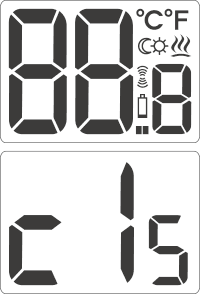
Once the batteries are properly inserted, the LCD display will show all segments for a second (display test), followed by the software version number. After a moment, the current room temperature will automatically be displayed. The controller is ready for operation.
Temperature setting
The first press of any function key always turns on the backlight, and only the next press activates the key function.
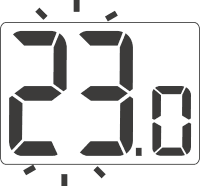
- Press the b or c . The temperature display segment will enter edit mode and start flashing.
- b and c buttons to set the desired temperature with an accuracy of 0.2°C.
- Confirm your selection by briefly pressing the d
FrostGuard function
AURATON 200 RT thermostat is equipped with a special "FrostGuard" function that protects the room from freezing. This function activates when the thermostat is turned off .
When the controller is off and the room temperature drops to 2°C, the symbols Fr (!) and a signal will be sent to the receiver, which will turn on the heating. When the temperature rises to 2.2°C, the display will turn off again and a signal will be sent to the receiver, which will turn off the heating.Setting the "temporary temperature reduction" mode
If, for various reasons, you'd like to lower the room temperature by 3°C at the same time each day, you can temporarily reduce it for 6 hours. To do this, follow these steps:
- b and c buttons for 3 seconds T ) will appear on the display
- The controller switches to the "temporary temperature reduction" mode and every day at the same time it will lower the temperature programmed in the normal mode by 3°C for a period of 6 hours.
After 6 hours, the thermostat will return to the basic temperature setting. Instead of the moon symbol ( T ), the sun symbol ( ) will appear on the screenS .
The "temporary temperature reduction" mode always begins when the function is enabled. This means that any temporary temperature reduction must be programmed at the time you want it to occur.
Turning off the "temporary temperature reduction" mode
To deactivate the "temporary temperature reduction" mode, press and hold the buttons again for 3 seconds. b cThe moon symbol on the display will go out (T) or sun (S) and only the room temperature will remain displayed. The controller has returned to normal operating mode.Hysteresis change
Hysteresis is designed to prevent the actuator from switching on too frequently due to minor temperature fluctuations.
For example, for HI 2 HI 4 hysteresis, with the temperature set to 20°C, the boiler will turn on at 19.6°C and turn off at 20.4°C.
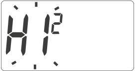
HI 2 – ±0.2°C (factory set)
HI 4 – ±0.4°C
HI P – PWM operating mode (chapter "PWM operating mode").
Confirm the selection with the d . The controller will return to normal operation.
PWM operating mode
(Pulse-Width Modulation)By changing the hysteresis settings (see the "Configuration Settings" section), you can enable PWM operation.
In this mode, the controller periodically turns on the heating device to minimize temperature fluctuations. The controller checks the temperature rise and fall times.
Knowing these values, the controller turns the heating device on and off in cycles to maintain the temperature as close to the setpoint as possible.
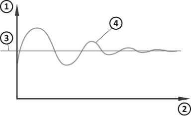
- Temperature
- Time
- Set temperature
- Room temperature
In PWM mode, the controller may turn on the heating device even if the room temperature is higher than the setpoint temperature. This is due to the PWM algorithm, which aims to maintain the setpoint temperature and anticipate the heating system's behavior.
Operation of the RT receiver with a heating device
Basic device configuration
 |
 |
|
AURATON RT |
AURATON 200 RT |
Additional system devices
 |
 |
|
AURATON T-2 |
AURATON H-1 |
Simplified diagram of connecting AURATON RT to a heating device
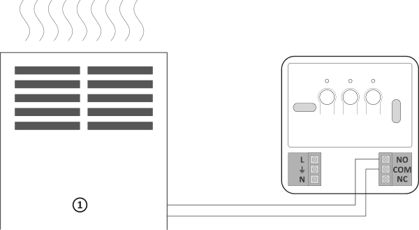
1 – heating device
Cooperation of the AURATON RT receiver with the AURATON 200 RT controller and/or the AURATON T-2 thermometer
The operation of the temperature control in the receiver is based on a two-state algorithm (on/off) using one or two sensor elements.
- The AURATON 200 RT controller allows you to set the temperature and/or control it continuously.
- The AURATON T-2 thermometer only provides information about the current temperature without the possibility of changing it manually.
- Manual setting – by pairing the AURATON 200 RT regulator with the RT receiver, we can manually set the temperature and control it at the location where the 200 RT regulator is mounted.
- Remote setting – if you pair a T-2 thermometer with the same RT receiver, the AURATON 200 RT regulator will retain its temperature setting capability, but control will only be performed by the paired T-2 thermometer. This allows you to control the temperature in a room other than the one where the
AURATON 200 RT regulator is located.
For example: If you want the "children's room" to always be at 22°C, but you don't want the children to be able to change the temperature, you can install the T-2 thermometer in that room and the AURATON 200 RT regulator, for example, in the kitchen. This solution ensures the "children's room" will always be at 22°C, regardless of temperature fluctuations in the kitchen. - Factory setting (20°C) – if only the T-2 thermometer is paired with the RT receiver, it will not be possible to manually set the temperature and the RT receiver will maintain the factory temperature setting of 20°C.
- The order in which the AURATON 200 RT regulator and the T-2 thermometer are paired is very important. If you want to implement remote setting, first pair the AURATON 200 RT regulator with the RT receiver, and then the T-2 thermometer. Reverse pairing will automatically deregister the previously paired T-2 thermometer and switch to the operating mode described in point 1.
- The RT receiver can only work with one AURATON 200 RT regulator and/or one T-2 thermometer. Pairing a new regulator will deregister the previously paired regulator and T-2 thermometer. Pairing a new T-2 thermometer will only deregister the previously paired T-2 thermometer.
- The 200 RT regulator and/or the T-2 thermometer can work with an infinite number of receivers, e.g. one regulator can control two independent heating devices simultaneously.
- When the AURATON 200 RT regulator is operated with a T-2 thermometer, the operation indicator on the 200 RT regulator display does not reflect the operation of the heating device.
Cooperation with the AURATON 200 RT regulator and/or the AURATONT-2 thermometer and the AURATON H-1 door handles
By default, the AURATON RT receiver does not have any AURATON H-1 handle paired, so the relay is controlled by the paired AURATON 200 RT regulator and/or AURATON T-2 thermometer. When at least one H-1 handle is paired with the RT receiver, the relay will be controlled as follows:
- Window closed or unsealed (micro-ventilation)
When we associate H-1 handles with the receiver and all windows are closed or unsealed, the relay still implements the setting from the associated AURATON 200 RT regulator and/or T-2 thermometer. - Window tilted
When even one window is tilted, the AURATON RT receiver will lower the set temperature of the AURATON 200 RT regulator by 3°C. This will last until all windows assigned to the RT receiver are closed or unsealed. Example: The AURATON 200 RT regulator is set to an actual temperature of 21°C. Then we tilt the window with the associated H-1 handle. The RT receiver will maintain a room temperature of 18°C . - Window Open:
When a window with an associated H-1 handle is opened for longer than 30 seconds, the relay in the AURATON RT receiver will be deactivated, and the heating device will also be turned off. If all assigned windows are again in a state other than open, the RT receiver will return to normal operation with the AURATON 200 RT regulator and/or T-2 thermometer no sooner than 90 seconds after the relay is turned off. This is an intentional delay to prevent excessively abrupt on-off transitions of the heating devices. However, if the room temperature were to drop below 7°C, regardless of the window position, the relay in the receiver will activate, turning on the heating device to prevent the room from freezing. - Signal Loss
When the RT receiver loses the signal from the associated H-1 handle (3 consecutive lost transmissions), it changes the status of this window to closed. Once transmission is restored, the H-1 handle is again correctly read by the RT receiver.
Special situations
- When 3 consecutive transmissions (after 15 minutes) from the AURATON 200 RT regulator and/or the T-2 thermometer are lost, a failure will be signalled on the RT receiver (the LED will continuously flash alternately in red and green). Until the problem is eliminated, the RT receiver will switch to the memorised on/off cycle from the last 24 hours.
- When both signals return (from the AURATON 200 RT regulator and the T-2 thermometer), the error is cleared and the receiver switches to normal operation.
- When the T-2 thermometer signal returns, the receiver uses the last saved setting and maintains it, continuing to signal the failure.
- When the H-1 handles, T-2 thermometer, and AURATON 200 RT regulator are paired with the receiver (temperature is measured by the T-2 thermometer), the operating cycle from the last 24 hours will be maintained only after the signal from the T-2 thermometer is lost. When only the signal from the AURATON 200 RT regulator is lost, the RT receiver automatically maintains the last saved setting of the AURATON 200 RT regulator, but also signals a failure.
- When only the H-1 handles and the T-2 thermometer are paired with the RT receiver without the AURATON 200 RT regulator, the RT receiver will maintain a constant factory-set temperature of 20°C. If you tilt any window with the paired H-1 handle, the temperature will be maintained at 17°C. If you open any window with the paired H-1 handle, the RT receiver will turn off the heating device, but will turn it back on if the temperature drops below 7°C.
Unique features of AURATON 200 RT
- The relay's switching is synchronized with the 230V mains supply voltage so that the relay's armature contacts always close and open at the zero crossing of the mains voltage. This prevents arcing and significantly increases the relay's durability.
- The AURATON RT receiver is equipped with a unique on-off cycle analysis algorithm. The entire heating cycle from the last 24 hours is saved in the RT receiver's memory. In the event of a loss of communication with the AURATON 200 RT controller and/or the T-2 thermometer, the RT receiver will automatically perform the memorized on/off cycle from the last 24 hours. This allows time to restore transmission (remove interference) or repair the 200 RT controller and/or the T-2 thermometer without significantly compromising thermal comfort in the controlled facility.
- Cooperation with optional devices (AURATON T-2 thermometer, AURATON H-1 window handle).
Additional information and notes
- The AURATON 200 RT regulator and/or the T-2 thermometer must be installed at least 1 meter from the RT receiver (too strong a signal from the transmitters may cause interference).
- At least 30 seconds must pass between the next switching of the relay off and on.
- Data is transmitted from the AURATON 200 RT controller to the receiver whenever the ambient temperature changes by 0.2°C. If the temperature remains constant, the controller transmits control data every 5 minutes (this is indicated by the LED on the RT receiver flashing orange).
- In the event of a power outage, the RT receiver will turn off. When power is restored, the heating device will automatically turn on, and the RT receiver will wait for the next signal from the paired transmitters (this signal should arrive no later than 5 minutes after power is restored). Once the signal is received, the RT receiver will resume normal operation.
- Do not place the RT receiver in metal housings (e.g. mounting box, metal furnace housing) so as not to interfere with the operation of the controller.
- The AURATON 200 RT controller can be turned on or off at any time by briefly pressing the d .
- The first press of any function key always turns on the backlight, and only the next press activates the key function.
- When programming any function in the AURATON 200 RT controller, not pressing any button for 10 seconds is equivalent to pressing the d .
Cleaning and maintenance
- Clean the exterior of the device with a dry cloth. Do not use solvents (such as benzene, thinner, or alcohol).
- Do not touch the device with wet hands. This may result in electric shock or serious damage to the device.
- Do not expose the device to excessive smoke or dust.
- Do not touch the screen with a sharp object.
- Avoid contact of the device with liquids or moisture.
Receiver connection diagram
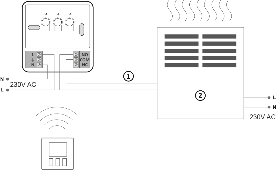
1 – control
2 – heating device, e.g. gas furnace

1 – electric heating device
2 – protective ( $ )
Technical data
| Operating temperature range: | 0 – 45°C |
| Temperature measurement range: | 0 – 35°C |
| Temperature control range: | 5 – 30°C |
| Hysteresis: | +/-0.2°C; +/-0.4°C PWM |
| Temperature setting accuracy: | 0.2°C |
| Temperature measurement accuracy: | 0.2°C |
| Default temperature setting: | 20°C |
| Additional function: | FrostGuard |
| Duty cycle: | daily |
| Operating status check: | LEDs (RT receiver) / LCD (controller) |
| Degree of protection: | IP20 |
| AURATON 200 RT power supply : | 2x AAA 1.5V alkaline batteries |
| RT transmitter power supply | 230V AC, 50Hz |
| Radio Frequency : | 868 MHz |
| RT operating range | in a typical building, with standard wall construction – approx. 30 m; in open areas – up to 300 m |
Disposing of the device
O
Devices are marked with a crossed-out waste bin symbol. In accordance with European Directive 2012/19/EU and the Waste Electrical and Electronic Equipment Act, this marking indicates that this equipment, after its useful life, must not be disposed of with other household waste.
Users are obligated to dispose of it at a collection point for used electrical and electronic equipment.