User manual ver. 20201007
This document collects information on the safety, installation and use of the AURATON Apus SET device.
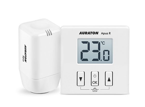
Daily, wireless temperature controller with electronic radiator head (set)
| U | FrostGuard function to protect the room from freezing. |
| & | Possibility of cyclically lowering the programmed temperature by 3°C for a period of 6 hours. |
| LCD | Illuminated LCD display The illuminated display allows you to monitor the device's operation even in poorly lit rooms. |
Basic information
The AURATON Apus SET is a set designed for controlling and regulating room temperature. The set consists of the AURATON Apus R wireless daily temperature controller and the AURATON Apus electronic radiator head. The AURATON Apus head is designed for installation on M30x1.5 radiator inserts and, using a special adapter, on Danfoss RA-N valves (adapter included) or on underfloor heating manifolds with a 30x1.5 mm thread. The AURATON Apus communicates wirelessly with the AURATON Apus R, collecting information about the current room temperature and the setpoint temperature. A single room can contain any number of radiators with AURATON Apus heads, or an underfloor heating manifold can have any number of circuits for a given room, but all of them must be paired with the same AURATON Apus R.
Description of AURATON Apus R
The front of the AURATON Apus R housing features a backlit LCD display and three function buttons.
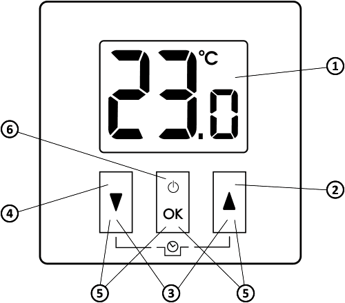
- LCD display
- Increase temperature button
- Temporary temperature reduction mode buttons
- Temperature reduction button
- Pairing buttons
- Confirmation button or controller on/off
| d |
|
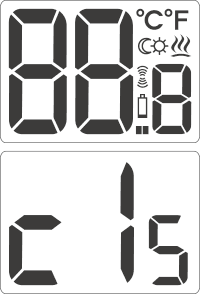
Display
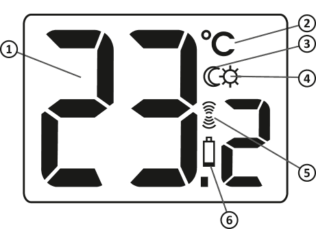
- Temperature
In normal operation mode, AURATON Apus R displays the temperature of the room in which it is installed. - Temperature unit (
R ) Indicates whether the temperature is displayed in degrees Celsius. - Temporary temperature reduction mode indicator (
T ) Active during the execution of the time temperature reduction program. - Temporary temperature reduction mode programming indicator (
S ) Indicates that the user has enabled temporary temperature reduction mode. Visible when the mode is not currently running, but the temporary temperature reduction function is active (more information in the "Setting the temporary temperature reduction mode" section). - Transmit Symbol (
W ) Indicates communication with the receiver. - Low Battery (
X ) This indicator appears when the battery voltage has exceeded the minimum allowable level. The batteries should be replaced as soon as possible.
Selecting the location of AURATON Apus R
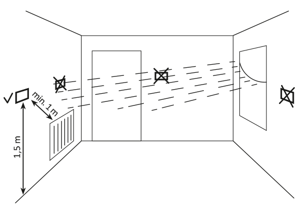
The proper operation of the AURATON Apus R is significantly affected by its location. Siting it in a location lacking air circulation or exposed to direct sunlight may result in improper temperature control. The AURATON Apus R should be installed on an interior wall (partition wall), in an environment with free air circulation. Avoid proximity to heat-emitting devices (TV, radiator, refrigerator) or locations exposed to direct sunlight. Proper operation may be impaired by proximity to doors, which expose the AURATON Apus R to potential vibration.
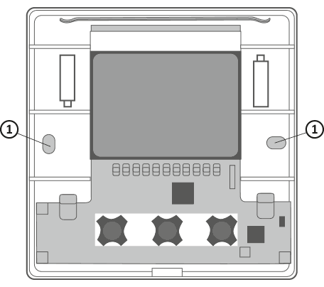
Battery installation/replacement
The battery compartments are located inside the AURATON Apus R on both sides of the display. To install the batteries, remove the AURATON Apus R casing as shown in the illustration.
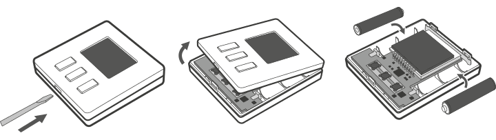
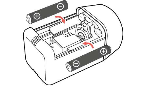
Insert two 1.5V AAA batteries into the battery compartment, paying attention to the correct polarity of the batteries.
We recommend alkaline batteries for powering AURATON controllers. Rechargeable batteries should not be used due to their low rated voltage.
AURATON Apus R mount
To attach AURATON Apus R to the wall:
- Remove the cover (as shown in the "Installation/Replacing the Battery" section).
- Drill two 6 mm diameter holes in the wall (mark the hole spacing using the rear part of the AURATON Apus R housing).
- Insert the expansion bolts into the drilled holes.
- Screw the rear part of the AURATON Apus R housing to the wall using the screws included in the kit.
- Install the batteries and put the cover on.
If you have a wooden wall, there is no need to use expansion bolts. Simply drill 2.7mm holes (instead of 6mm) and drive the screws directly into the wood.
Do not mount the AURATON Apus R controller on metal surfaces, as this significantly reduces the range of radio communication.
- Holes for mounting screws.
Alternative mounting methods
The AURATON Apus R can be attached to a smooth surface using double-sided tape, for example. The AURATON Apus R can also be placed anywhere on a flat surface using the stand located on the rear of the housing.
First launch of AURATON Apus R
Once the batteries are properly inserted, the LCD display will show all segments for a second (display test), followed by the software version number. After a moment, the current temperature will be displayed. The AURATON Apus R is ready for operation.
Temperature setting
The first press of any function button always turns on the backlight, and only the next press activates the button function.
- Press the b or c . The temperature display segment will enter edit mode and start flashing.
- b and c buttons to set the desired (set) temperature with an accuracy of 0.2°C
- Confirm your selection by briefly pressing the d
FrostGuard function
The AURATON Apus R is equipped with a special FrostGuard function that protects the room from freezing. This function is activated even when the AURATON Apus R is turned off .
When the AURATON Apus R is turned off and the room temperature drops to 2°C, the symbols (!) and a signal will be sent to the head, which will turn on the heating. When the temperature rises to 2.2°C, the display will turn off again and a signal will be sent to the head, which will turn off the heating.Setting the time mode for temperature reduction
If you'd like to lower the room temperature by 3°C at the same time each day, you can temporarily reduce it for 6 hours. To do this, follow these steps:
- b and c buttons for 3 seconds T ) will appear on the display
- AURATON Apus R switches to temporary temperature reduction mode and every day at the same time it will lower the temperature programmed in normal mode by 3°C for a period of 6 hours.
After 6 hours, AURATON Apus R will return to the basic temperature setting. Instead of the moon symbol ( T ), the sun symbol ( ) will appear on the screenS .
The "temporary temperature reduction" mode always begins when the function is enabled. This means that any temporary temperature reduction must be programmed at the time you want it to occur.
Enabling the temporary 3°C temperature reduction function does not guarantee that such a reduction will occur within 6 hours. This depends on the building's thermal inertia.
Turning off the "temporary temperature reduction" mode
To deactivate the "temporary temperature reduction" mode, press and hold the buttons again for 3 seconds. b cThe moon symbol on the display will go out (T) or sun (S) and only the room temperature will remain displayed. AURATON Apus R has returned to normal operating mode.Description of AURATON Apus
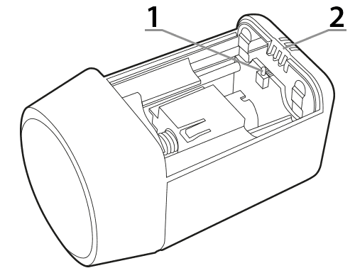
The AURATON Apus head works with the AURATON Apus R wireless controller. The head is mounted directly on the radiator or underfloor heating manifold.
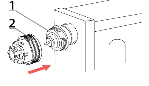
- – Battery cover closing, pairing and reset button.
- – Indicator diode.
AURATON Apus installation
Radiator with M30x1.5 insert
or underfloor heating distributor
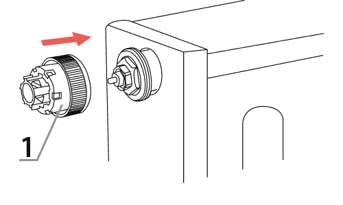
To mount AURATON Apus on a radiator or underfloor heating manifold with an M30x1.5 insert, perform the following steps:
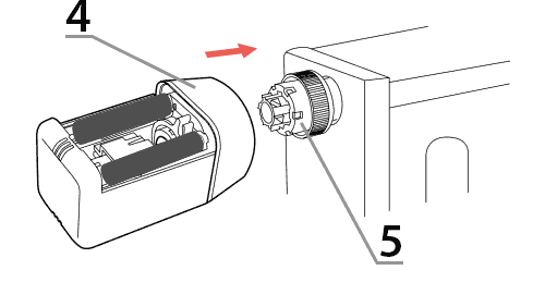
- Screw the reduction A (1) included in the AURATON Apus kit onto the insert (as far as it will go).
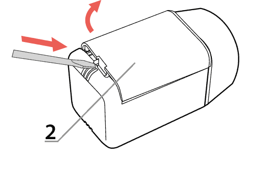
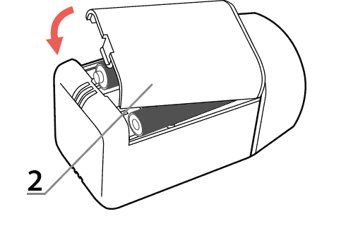
- Remove the battery cover (2) of the AURATON Apus using a flat screwdriver.
- Install two AAA batteries into the AURATON Apus, observing polarity. The head pin will move to the fully open position, making it easier to mount the AURATON Apus on the adapter.
- Move the locking ring (3) to the “unlocked” position.
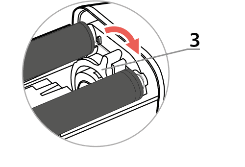
- Slide the AURATON Apus (4) onto the reduction A (5) as far as it will go.
- Turn the locking ring (3) to the “secured” position.

- Perform the pairing procedure with AURATON Apus R if such procedure has not been performed before.
- Close the battery cover (2) of the Auraton Apus.
Radiator with Danfoss RA-N insert
To install AURATON Apus on a radiator with a Danfoss RA-N insert:
- Place 2 halves of the B reduction (1)
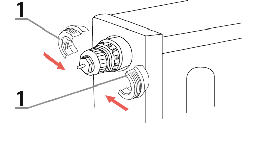
- On the assembled reduction B (1), tighten the reduction A (2)
- Carry out steps 2 to 8 in the Radiator with M30x1.5” insert section
Device pairing
For the AURATON Apus head to work correctly, it must be paired with the AURATON Apus R controller. The pairing process is as follows:
- Restore the AURATON Apus to factory settings (see the section "Restoring the head to factory settings")
- In AURATON Apus R b d or c d buttons simultaneously for more than 3 seconds.
- After a 3-second countdown, AURATON Apus R will send its identifier to AURATON Apus, which will be signaled by the head with a triple beep.
- Once the AURATON Apus R has been successfully paired with the AURATON Apus, close the battery cover (if it was already mounted on the radiator).
If the first pairing fails, perform a factory reset , move closer to the AURATON Apus and pair again.
The AURATON Apus R wireless controller sold with the AURATON Apus head is already paired. Devices purchased separately require pairing.
AURAON Apus R communication with AURATON Apus and error indication
To conserve battery power, the AURATON Apus R communicates with the AURATON Apus periodically every 2 minutes. Immediately after pairing the AURATON Apus R with the AURATON Apus, a synchronization process occurs, lasting approximately one minute. This synchronization is not signaled but is necessary for the set to function properly.
If radio communication is disrupted, e.g. due to a depleted battery in the AURATON Apus R or during its replacement, the AURATON Apus will signal a loss of connection by lighting the LED every 8[s] after 6 minutes. After a maximum of 4 hours, the head should automatically resynchronize with the AURATON Apus R. This time can be shortened to 2 minutes if, after losing synchronization, the cover is removed from the AURATON Apus and reattached.
Even if communication between the AURATON Apus R and the AURATON Apus is disrupted, the user should not experience any deterioration in comfort. The AURATON Apus will automatically stabilize the room temperature at the level it remembered before losing communication with the AURATON Apus R.
Signaling after starting AURATON Apus
After inserting the batteries, the AURATON Apus signals its readiness with an audible signal and an LED. Two scenarios are possible:
- A single beep means that the AURATON Apus is already paired with the AURATON Apus R. Simply mount the AURATON Apus on the radiator insert or underfloor heating manifold and close the battery cover. After approximately 30 [s], the AURATON Apus will start regulating the temperature.
- triple beep – AURATON Apus is not paired with AURATON Apus R. After closing the battery cover, AURATON Apus WILL NOT execute the temperature regulation algorithm. It is necessary to complete the pairing process described in the Pairing Devices section.
If the AURATON Apus pressure pin was not in the fully open position, the motor will also start and the actuator will move to the rear position to facilitate the installation of the AURATON Apus.
Calibration error indication
After mounting on a radiator or underfloor heating manifold and closing the battery cover, the AURATON Apus calibrates the mechanical system. If an error occurs during calibration, it is signaled audibly by the speaker sounding for 1 second every 1 second. If a calibration error occurs, check the following:
- Is the A reduction properly screwed to the radiator insert or underfloor heating manifold?
- Is the B reduction (in the case of Danfoss inserts) correctly fastened to the insert and is the A reduction correctly screwed into the B reduction?
- Is the locking ring correctly set to the “secured” position?
- Are the installed batteries discharged (see chapter: "Radiator with M30x1.5 insert or underfloor heating manifold" points 2 and 3)
- If the above-mentioned actions do not result in correct calibration, this may indicate incorrect operation of the radiator valve or underfloor heating manifold itself, or incompatibility of AURATON Apus with this valve.
Assembly instructions
The AURATON Apus R should be placed in a room where there is an AURATON Apus with a radiator or in a room to which appropriate underfloor heating circuits are connected. It should not be placed next to a radiator, near a door, or in direct sunlight.
Battery life
The declared operating time on a single set of AAA alkaline batteries is one year. Discharging the batteries does not affect temperature control. The AURATON Apus signals a low battery by flashing the LED twice every 8 seconds. Additionally, when the battery becomes even more discharged, the head will begin to emit a double beep every 8 minutes. To turn off the audible signal for 24 hours, press any key on the AURATON Apus R paired with the AURATON Apus, or lift the AURATON Apus cover for 2 seconds and replace it.
After 24 hours, the signal will turn on again, reminding you to replace the batteries. You can then turn the signal off again for another 24 hours, but this process will repeat until the batteries are replaced.
Unique features of AURATON Apus SET
- Auraton Apus R and Auraton Apus "learn" the room in the first phase of use to control the heating as precisely as possible.
- Initially, temperature fluctuations may be greater, but will decrease over time.
Cleaning and maintenance
- Clean the exterior of the device with a dry cloth. Do not use solvents (such as benzene, thinner, or alcohol).
- Do not touch the device with wet hands. This may cause serious damage to the device.
- Do not expose the device to excessive smoke or dust.
- Do not touch the screen with a sharp object.
- Avoid contact of the device with liquids or moisture.
RESET – restoring factory settings AURATON Apus
- Remove the AURATON Apus battery cover.
- Remove the battery (one is enough).
- Press the battery cover close button (located on the electronics board between the batteries.)
- While holding the button down, install the batteries and wait approximately 4 seconds.
- When you hear three beeps, release the button.
Technical data
| Operating temperature range: | 0 – 45°C |
| Temperature measurement range: | 0 – 35°C |
| Range of action: | in a typical building, with standard wall construction – approx. 30 m; in open areas – up to 300 m |
| Radio frequency: | 869,000 MHz |
| Radio signal strength: | Up to 11 dBm |
| Degree of protection: | IP20 |
AURATON Apus R:
| Power supply: | 2 x AAA (2 x 1.5 V), alkaline |
| Operating status indication: | LCD display |
| Number of temperature levels: | 1 |
| Antifreeze temperature: | 2°C |
| Temperature control range: | 5 – 30°C (measurement error +/- 1°C) |
| Temperature setting accuracy: | 0.2°C |
| Temperature measurement accuracy: | ±0.1°C |
| Duty cycle: | Daily |
| Dimensions [mm]: | 70 x 70 x 14.5 |
AURATON Apus:
| Power supply: | 2 x AAA (2 x 1.5 V), alkaline |
| Operating status indication: | LED diodes, sound |
| Suggested mounting location: | Radiator, underfloor heating distributor |
| Dimensions [mm]: | 75 x 40 x 40 |
Disposal of the device
O
Devices are marked with a crossed-out waste bin symbol. In accordance with European Directive 2012/19/EU and the Waste Electrical and Electronic Equipment Act, this marking indicates that this equipment, after its useful life, must not be disposed of with other household waste.
Users are obligated to dispose of it at a collection point for used electrical and electronic equipment.
LARS Andrzej Szymański hereby declares that the radio equipment type AURATON Apus SET is in compliance with Directive 2014/53/EU and 2011/65/EU. The full text of the EU declaration of conformity is available in the download section below.
Manufacturer's address
Lars
ul. Świerkowa 14
64-320 Niepruszewo
Poland
www.auraton.pl