User manual ver. 20211103
This document collects information regarding the safety, installation and use of the AURATON Cetus device.
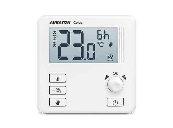
Daily, wired temperature controller
AURATON Cetus is a daily, wired temperature controller designed to work with a gas or electric heating device.
| U | “FrostGuard” function protects the room from freezing. |
| & | Possibility of temporarily lowering the programmed temperature for a maximum period of 12 hours. |
| Z | Holiday mode Up to eight days independent of the programmed temperature. |
| LCD | Illuminated LCD display The illuminated display allows you to monitor the device's operation even in poorly lit rooms. |
Description of AURATON Cetus
daily, wired temperature controller
On the front of the controller housing there is a backlit LCD display, four function buttons and a temperature setting knob with a button. (.
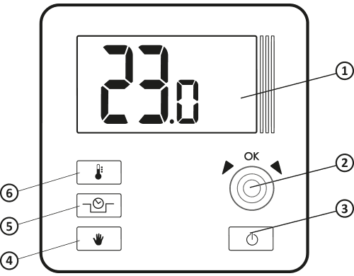
- LCD display
- Settings knob with integrated button (
- Controller on/off button
- Manual mode button
- Temporary temperature reduction mode button
- Temperature setting button
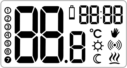
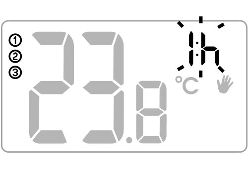
Display
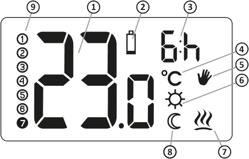
- Temperature – In normal operation mode, AURATON Cetus displays the temperature of the room in which it is installed.
- Low Battery ( X )
This indicator appears when the minimum permissible battery voltage level has been exceeded. The batteries should be replaced as soon as possible.
NOTE: To maintain programmed parameters, the battery replacement operation should take no longer than 30 seconds. - "Temporary temperature reduction" duration indicator
Indicates how long the "temporary temperature reduction" mode will remain active. - Temperature unit
Indicates whether the temperature is displayed in degrees Celsius ( R ). - Manual mode indicator ( V )
Indicates that the unit has switched to manual (holiday) temperature setting mode. - Temporary temperature reduction mode programming indicator ( S )
Indicates the user-programmed "temporary temperature reduction" mode. Appears when the mode is not currently running, but the "temporary temperature reduction" function is active. (More information in the "Setting the Temporary Temperature Reduction Mode" section) - AURATON Cetus On Indicator ( a )
Pictogram informing about the device's operating status. Visible when the controlled device is turned on. - Temporary temperature reduction mode indicator ( T )
Appears when the timed temperature reduction program is in progress. - Number of days in vacation mode ( 8 )
Indicates the number of days for which vacation mode is scheduled.
Choosing the right location for AURATON Cetus
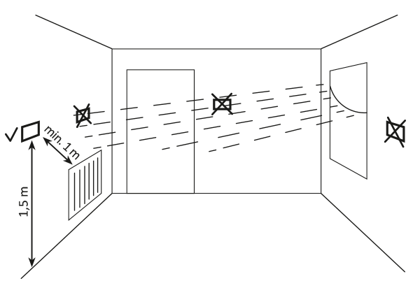
The proper operation of the AURATON Cetus is significantly affected by its location. Siting it in a location lacking air circulation or exposed to direct sunlight may result in improper temperature control. The AURATON Cetus should be installed on an interior wall (partition wall), in an environment with free air circulation. Avoid proximity to heat-emitting devices (television, radiator, refrigerator) or locations exposed to direct sunlight. Proper operation may be impaired by proximity to doors, which expose the AURATON Cetus to potential vibration.
Connecting the cables to AURATON Cetus
To connect the cables, remove the housing as shown below:
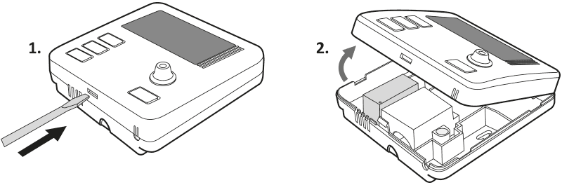
The cable terminals are located on the rear wall of the AURATON Cetus, under a plastic cover.

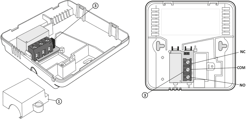
- cover
- screw
- cable clamps
This is a typical single-pole, two-state relay. In most cases, the NC terminal is not used.
After connecting the wires, reinstall the plastic cover.
Battery replacement
The battery compartment is located inside the AURATON Cetus on the front of the housing. To install the batteries, remove the controller housing as shown in the "Connecting the cables to the AURATON Cetus" section.
We recommend alkaline batteries for powering AURATON controllers. Rechargeable batteries should not be used due to their low rated voltage.
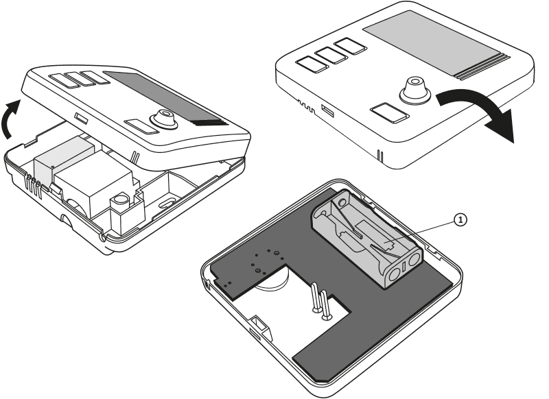
- – 1.5V AAA battery slot
Insert two 1.5V AAA batteries into the battery compartment, paying attention to the correct polarity of the batteries.
After replacing the batteries and reassembling the housing, we recommend pressing the button twice( to stabilize the relay operation.
Mounting the AURATON Cetus – a daily, wired temperature controller
To attach the AURATON Cetus regulator to the wall:
- Remove the controller housing (as shown in the section "Connecting the cables to AURATON Cetus")
- Drill two 6 mm diameter holes in the wall (mark the hole spacing using the rear part of the AURATON Cetus housing).
- Insert the expansion bolts into the drilled holes.
- Screw the rear part of the AURATON Cetus housing to the wall using the screws included in the kit.
- Put on the AURATON Cetus housing.
If you have a wooden wall, there is no need to use expansion bolts. Simply drill 2.7mm holes (instead of 6mm) and drive the screws directly into the wood.
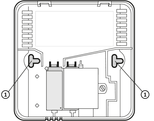
- hole for the mounting screw
Attaching the casing: NOTE
When putting the front part of the housing back onto the back, pay attention to the pins that control the relay.
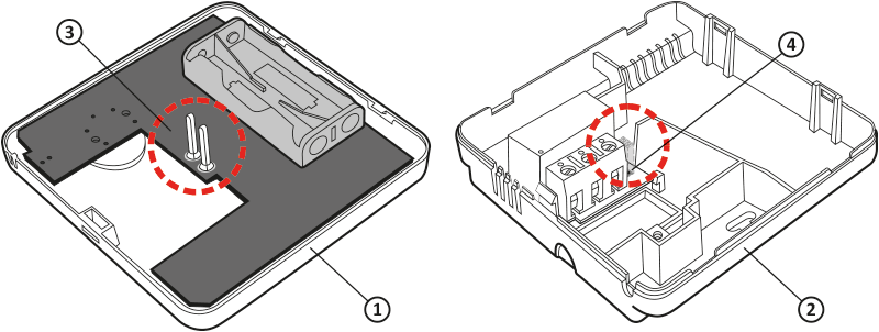
- Front cover
- Back cover
- Pins
- Pin connector socket or the point where the pins contact the board
When assembling the housing, ensure that the connection pins are not bent and that they fit correctly on the relay board. This is crucial for the proper operation of the controller.
First launch of AURATON Cetus
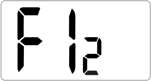
Once the batteries are properly inserted into the slots, the LCD will display all segments for a second (display test) followed by the software version number (e.g. F12).
After a moment, the current room temperature will be automatically displayed. AURATON Cetus is ready for operation.
Temperature setting
The first press of any function button always turns on the backlight, and only the next press activates the button function.
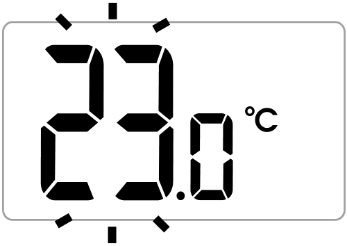
After a moment, the current room temperature will be automatically displayed. AURATON Cetus is ready for operation. To set the desired temperature in normal operation mode:
- Press the buttonn . The segment displaying the current room temperature will start flashing.
- By turning the knob left or right, with an accuracy of 0.2°C, we set the desired temperature in the room.
- Confirm your selection with the button (
Setting the "temporary temperature reduction" mode
If, for various reasons, you would like to lower the room temperature at a certain time each day, you can temporarily reduce it by up to 5°C. To do this, you must:
- Press and hold the button for 3 seconds& . The display will show the moon ( T ), the hour field (e.g. * ), and the temperature segment will enter edit mode and start flashing.
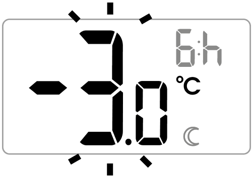
- By turning the knob left or right, you set the temperature reduction by a value from 1°C to 5°C. Confirm your selection by pressing the button. (.
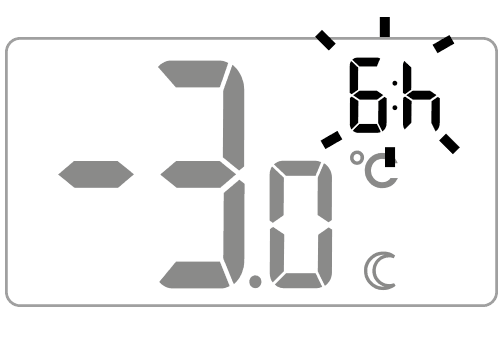
- The hour field on the display will enter edit mode and begin flashing. Using the knob again, set the number of hours for which the programmed reduced temperature will be in effect. You can choose from 1 to 12 hours. Confirm your selection by pressing the button. (.
- For the selected number of hours, AURATON Cetus will be in "temporary temperature reduction" mode and will activate it every day at the same time.
After the set hour, AURATON Cetus will return to the basic temperature setting. Instead of the moon (T S) will appear on the screen.
Temporary temperature reduction mode always begins when the function is confirmed. This means that any temporary temperature reduction should be programmed at the time you want the change to occur.
Turning off the "temporary temperature reduction" mode
AURATON Cetus will perform the programmed temporary temperature reduction mode every day at the same time until the temporary reduction is deactivated. To deactivate, press and hold the button again for 3 seconds. &.
Manual mode setting
If you'd like to temporarily suspend the normal or temporarily reduced temperature, you can set a "manual" program that will last for a maximum of 8 days. To do this, follow these steps:
- Press the buttono .
A hand symbol ( ) will appear on the displayV and the segment displaying the current temperature will enter edit mode and start flashing.
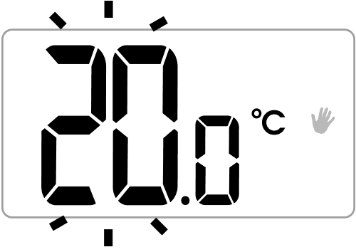
- Turn the knob left or right to set the desired temperature. Confirm your selection by pressing the button. (.
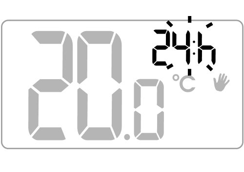
- The hour field on the display will enter edit mode and begin flashing. Use the knob to select the number of hours for which the manual temperature setting will apply. Days are added or subtracted automatically after the 24-hour period is exceeded. You can select a maximum of 7 days and 24 hours. Confirm your selection by pressing the button. (.
Manual mode is not automatically repeated. After the programmed time elapses, AURATON Cetus returns to the previous temperature programs: normal mode and temporary temperature reduction if the latter was previously scheduled.
Early deactivation of "manual" mode
AURATON Cetus will continue to operate in manual mode until the programmed time elapses. To exit manual mode sooner, press the button againo .
Checking the set temperature
Holding the button ( for at least 2 seconds allows you to check the currently programmed temperature of the controller. Correct execution of this operation results in a flashing segment on the display, indicating the set temperature of the device. This function is active in all AURATON Cetus operating modes.FrostGuard function
The AURATON Cetus is equipped with a special FrostGuard function that protects the room from freezing. This function activates when the AURATON Cetus is turned off .
!) and (a symbols appear on the display and the relay engages. When the temperature rises to 2.2°C, the display turns off again and the relay disconnects.
Hysteresis change
Hysteresis is designed to prevent the actuator from switching on too frequently due to minor temperature fluctuations.
For example, for HI 2 , with the temperature set to 20°C, switching on will occur at 19.8°C and switching off at 20.2°C. For HI 4 , with the temperature set to 20°C, switching on will occur at 19.6°C and switching off at 20.4°C.
To enter the hysteresis change mode, hold down the n , & and V for 3 seconds.
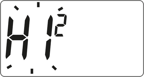
The hysteresis change mode is indicated by the flashing HI sign. Turn the knob left or right to set the desired hysteresis.
HI 2 – ±0.2 °C (factory setting),
HI 4 – ±0.4 °C,
HI P – PWM operating mode (section “PWM operating mode”).
Confirm the selection by pressing the button( . The controller will return to normal operation.
PWM operating mode
(Pulse-Width Modulation)PWM operation In this mode, AURATON Cetus periodically switches the heating device on to minimize temperature fluctuations. AURATON Cetus checks the temperature rise and fall times.
Knowing these values, AURATON Cetus turns the heating device on and off in cycles to keep the temperature as close to the set point as possible.
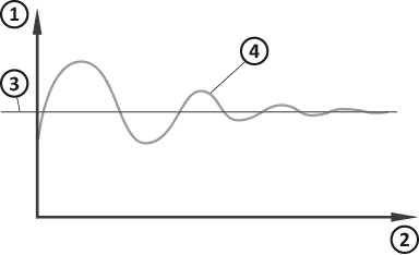
- Temperature
- Time
- Set temperature
- Room temperature
In PWM mode, AURATON Cetus may turn on the heating device even if the room temperature is higher than the setpoint temperature. This is due to the PWM algorithm, which aims to maintain the setpoint temperature and anticipate the heating system's behavior.
Comments
- AURATON Cetus can be turned on or off at any time by briefly pressing the button +.
- The first press of any function button always turns on the backlight, and only the next press activates the button's function. When using the knob, each step keeps the backlight on.
- When programming any function, not pressing any button for 10 seconds is equivalent to pressing the button. +.
- After switching off the relay (heating function), it can be switched on again no sooner than after 90 seconds.
AURATON Cetus connection diagram
AURATON Cetus can work with a gas OR electric heating device.
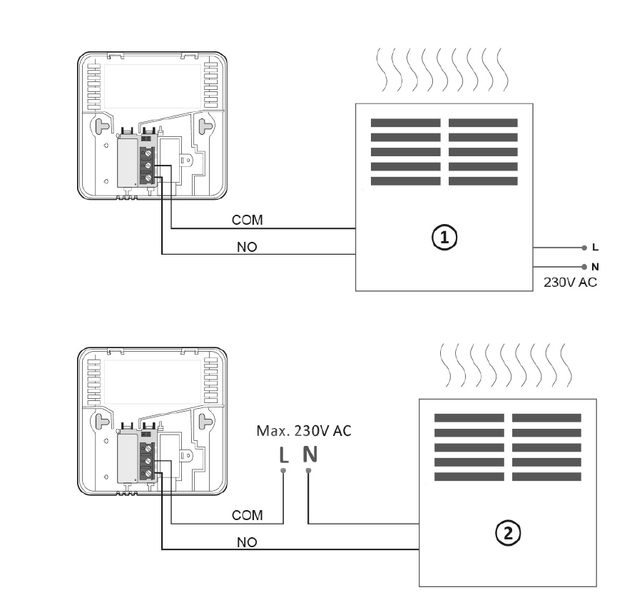
- A heating device , e.g. a gas furnace
- Electric heating device (MAX 230 V AC, 16 A)
Cleaning and maintenance
- Clean the exterior of the device with a dry cloth. Do not use solvents (such as benzene, thinner, or alcohol).
- Do not touch the device with wet hands. This may result in electric shock or serious damage to the device.
- Do not expose the device to excessive smoke or dust.
- Do not touch the screen with a sharp object.
- Avoid contact of the device with liquids or moisture.
Technical data
| Power supply: | 2 x AAA (2 x 1.5 V), alkaline |
| Operating temperature range: | 0 – 45°C |
| Operating status indication: | LCD display |
| Number of temperature levels: | 1 |
| Antifreeze temperature: | 2°C |
| Temperature measurement range: | 0 – 35°C (measurement error +/- 1°C) |
| Temperature control range: | 5 – 35°C |
| Temperature setting accuracy: | 0.2°C |
| Hysteresis: | ±0.2°C / ±0.4°C / PWM |
| Relay load capacity: | Max. 250 V AC, max. 16 A |
| Duty cycle: | Daily |
| Degree of protection: | IP20 |
| Dimensions [mm]: | 90 x 90 x 36 |
Disposal of the device
O
Devices are marked with a crossed-out waste bin symbol. In accordance with European Directive 2012/19/EU and the Waste Electrical and Electronic Equipment Act, this marking indicates that this equipment, after its useful life, must not be disposed of with other household waste.
Users are obligated to dispose of it at a collection point for used electrical and electronic equipment.
Manufacturer's address and contact details:
LARS, ul. Świerkowa 14
64-320 Niepruszewo
www.auraton.pl