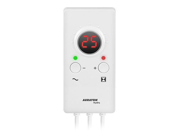
AURATON Hydra
User manual ver. 20210116
The document presents collected information on safety, assembly and use of AURATON Hydra.
Description of the device
The AURATON Hydra is designed to control a three-way valve – it closes and opens the valve within the hysteresis range of 10 °C. AURATON Hydra can operate both actuators with limit switches (AUTO function) and without limit switches (MANUAL function).
When using actuators with limit switches, use the AUTO function (the AURATON Hydra will automatically select the valve opening and closing times), while when using an actuator without limit switches, use the MANUAL function (manually select the operating time specified by the actuator manufacturer).
Installation
Temperature sensor mounting
- Install the sensor on an exposed pipe.
- Use a cable tie to press the sensor against the pipe.
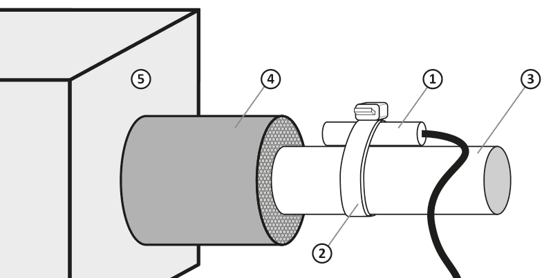
- temperature sensor
- cable tie
- pipe
- pipe insulation
- central heating furnace
Connecting the power supply wire to the valve
- On the controller side the blue wire is the common wire (in the actuator the common wire may be different depending on the manufacturer).
- The brown and black wires are control wires, depending on the direction of operation these two wires can be interchanged.
Connecting the AURATON Hydra
After securing the wires against accidental breaking, the power supply wire should be connected to the 230 V AC mains socket.
Installing the AURATON Hydra:
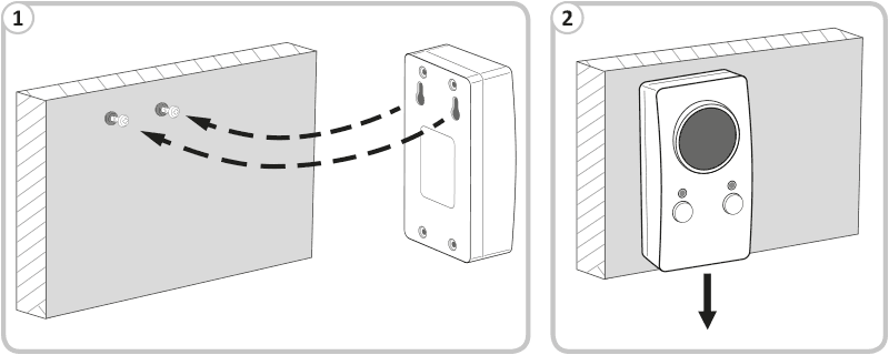
- Install the AURATON Hydra on a wall or bracket using two screws (wall plugs included).
- Wires leading from the AURATON Hydra should be fixed to the wall.
Operation of the AURATON Hydra
Setting the return temperature at 60 °C causes the opening and closing of the valve within the hysteresis range of ±5 °C. This means that when the sensor mounted on the return reaches a temperature of 65 °C, the valve will be fully closed, and at 55 °C it will be fully open. When the temperature set by the user on the controller at 60 °C is reached, the valve will be half open (50 %). The controller controls the valve like a stepper motor. Depending on the return temperature, it gradually opens or closes the valve. Every 1 °C change in temperature opens or closes the valve by 10 %.
Description of AURATON Hydra
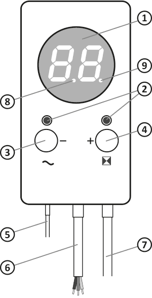
- LED display
- indicator lights
- function button/power switch
- function button/operating mode
- temperature sensor
- pump control output
- power supply wire
- valve opening indicator light
- valve closing indicator light
The valve opening and closing indicator lights are used to visualise the actuator operation. The blinking of the lights indicates the valve operation to the left or to the right.
First start-up of the AURATON Hydra
The mains switch button (®) is located on the left side, under the display. By holding it for 2 seconds the AURATON Hydra can be switched on or off. When the AURATON Hydra is switched off, the LED lights up red, whereas when the AURATON Hydra is switched on, the LED lights up green.
Upon start-up, the AURATON Hydra automatically calibrates the valve opening and closing time (the display reads ¤). It consists in the complete opening and closing of the valve and measuring its time. This value remains stored in the memory. For accurate measurement calibration is performed twice.
After the calibration process is completed, the display shows the current sensor temperature. The controller is ready to set the appropriate operating temperature.

Setting the temperature
Briefly press the left or right button to activate the temperature setting function.
The temperature on the display will flash for 3 seconds. During this time the (–) or (+) buttons can be used to set the desired temperature value.
Once the selection has been made, the AURATON Hydra will automatically save this value and the display will show the current sensor temperature.
If the actuator has limit switches, the AURATON Hydra is already ready for operation. If an actuator without limit switches is used, the operating time setting specified by the actuator manufacturer is required.
Setting the actuator operating time
Hold down the right (µ) button for 2 seconds to start editing the operating time of the actuator.
The display will read ´ (automatic operation).
Then, using the (–) or (+) buttons, set the appropriate time value:
- 01 – 10 seconds (minimum value)
- 40 – 400 seconds (maximum value)
- ´ – automatic operation
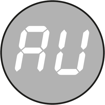
Setting the value to ´ means that the AURATON Hydra will again operate in automatic mode (actuator with limit switches).
When the editing is finished, the AURATON Hydra will save the entered values and the display will show the current temperature instead of the flashing time setting after 10 seconds.
The most common value is 150 seconds (15).
After power failure and restarting, ¶ will be visible (manual actuator time setting).

n the event of a momentary power failure, the AUTOCALIBRATION function is activated, after the calibration is completed the AURATON Hydra proceeds with normal operation.
The display will show: display test, software version (e.g. F1.2), the text ´ (automatic actuator operating time) or ¶ (actuator operating time set manually) and then the text ¤, which indicates that the calibration function is activated.
Switching off the AURATON Hydra
The controller can be switched off in two ways:
- During normal operation hold down the (®) button for 2 seconds, the display will go blank and the LED will change from green to red. The AURATON Hydra can also be switched off in the same way when performing the calibration function. The display will also go blank and the LED will change colour from green to red, but in this case the actuator direction indicator will blink. Thus, the calibration will be completed and the valve will be set in the middle position at 50 % (right LED orange).
- The second way is to completely switch off the AURATON Hydra at any time. This is done by simultaneously holding down both buttons for 2 seconds (® and µ). In this case the GUARD system will not be active. Complete switching off of the AURATON Hydra is indicated by both the left and right diode lighting up red. In order to switch the controller on again, the (®) button should be pressed.
Error information codes
| · | Valve calibration time too short in either direction (valve defect, wrong connection). | Valve stopped, waiting for error rectification (message only in ´ mode), press any key after error rectification. |
| « | Limit switch not engaged for more than 4 minutes (valve defective, bad connection). | Valve stopped, waiting for error rectification (message only in ´ mode), press any key after error rectification. NOTE: the appearance of this message at the first start-up of the AURATON Hydra may indicate the necessity to switch the AURATON Hydra to the ¶ mode (manual setting of the actuator operation time). |
| ° | No network synchronisation signal to protect the relay | Stopping of the valve, waiting for elimination of the fault (waiting for momentary disconnection of the power supply). |
| ± | A short circuit has occurred on the sensor | Valve stopping, awaiting elimination of the fault (replacement of temperature sensor), after elimination of the fault press any button. |
| ¬ | No sensor, sensor defective | Valve stopping, awaiting elimination of the fault (replacement of temperature sensor), after elimination of the fault press any button. |
| § | Sensor temperature below 2 °C | Valve stopped, awaiting correction of the error (temperature increase). |
| ¦ | Sensor temperature above 90 °C | Warning of excessively high system temperature. |
Any defects should be removed with the power supply disconnected from the mains socket.
The occurrence of the above alarms is signalled by an intermittent sound signal until the fault is removed or the AURATON Hydra is switched off. After removing the fault, the AURATON Hydra performs calibration and proceeds with normal operation.
Error codes are displayed alternately with the current sensor temperature (not applicable to code ± and ¬.
Other information codes
| ¤ | AURATON Hydra in valve calibration mode. |
| ´ | AURATON Hydra set to automatic actuator operating time. |
| ¶ | AURATON Hydra set to manual actuator operating time. |
GUARD function
AURATON Hydra is equipped with a GUARD function. Autocalibration is automatically started every 14 days. The purpose of this is to improve the precision of the actuator’s work and at the same time to prevent the process of stagnation of an unused valve.
The GUARD function is also active when the AURATON Hydra is switched off, but only after full calibration. It is signalled by only the left LED lighting up red.
AURATON Hydra operating modes
AURATON Hydra switched on (GUARD system active)
- left LED green
- display on
- right LED in colour depending on valve opening status:
green – valve closed,
orange – valve 50% open,
red – valve open.
AURATON Hydra in standby/off (GUARD system active)
- left LED red,
- display off,
- right LED off.
AURATON Hydra completely switched off (GUARD system inactive)
- left LED red,
- display off,
- right LED red.
Wiring diagram
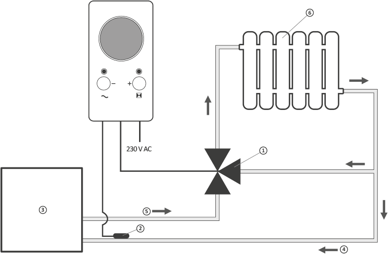
- mixing valve with actuator
- return temperature sensor
- central heating furnace
- cold water
- hot water
- heat receiver (e.g. radiator)
4-way valve wiring diagram
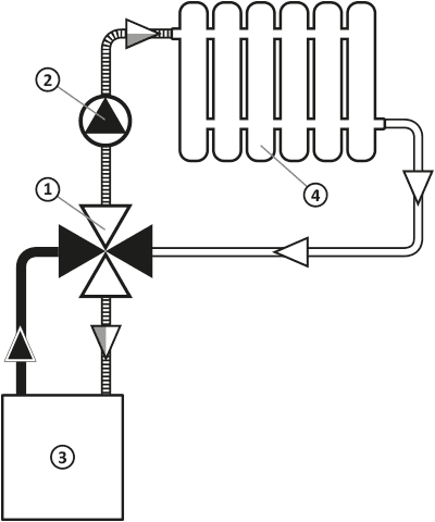
- 4-way valve with actuator
- pump
- central heating furnace
- heat receiver (e.g. radiator)
Cleaning and maintenance
- Clean the outside of the unit with a dry cloth. Do not use solvents (such as benzene, thinner or alcohol).
- Do not touch the unit with wet hands. Doing so may result in an electric shock or serious damage to the unit.
- Do not expose the unit to excessive smoke or dust.
- Do not touch the screen with a sharp object.
- Avoid contact of the device with liquids or moisture.
Technical specifications
| Power supply: | 230 V AC, 50 Hz, 1.5 W |
| Working temperature range: | 0 – 40 °C |
| Signalling the working status: | LED display, sound |
| Temperature control range: | 10 – 90 °C |
| Temperature measurement range: | 2 – 99 °C |
| Actuator operation time setting range: | 10 – 400 sekund |
| Hysteresis: | ±5 °C |
| Relay load capacity: | Max. 250 V AC, max. 1 A |
| Level of security: | IP20 |
| Dimensions [mm]: | 69.5 x 139.5 x 39 |
Disposing of the devices
O
The devices are marked with the crossed-out wheeled bin. According to European Directive 2012/19/EU and the Waste Electrical and Electronic Equipment Act, this kind of marking indicates that the equipment, after its operational life must not be disposed of together with other waste from households.
The user shall return it to a collection point for electrical and electronic waste.
Address and manufacturer contact details:
LARS, ul. Świerkowa 14
64-320 Niepruszewo
www.auraton.pl