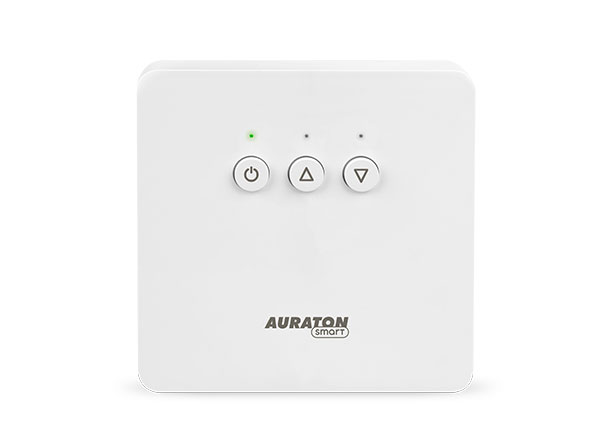
Heater Controller
User manual ver. 20201102
The document presents collected information on safety, assembly and use of Auraton Heater Controller.
Basic information
Auraton Heater Controller is a thermostatic device, which triggers heating e.g. by a boiler and it cooperates with wireless AURATON Heat Monitor. The device is mounted close to the heating device and may work under the load of 16A.
Description of the device
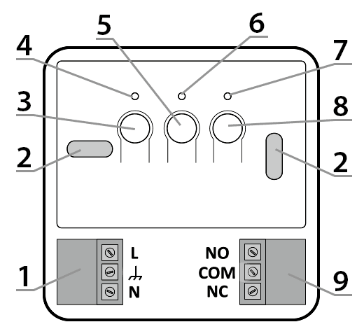
- – Detachable power connector terminals 230V
- – Installation opening
- – ON/OFF button ( F )
- – Power LED (green)
- – Button for restoring factory settings ( E )
- – Red LED indicating activation of an executive device
- – Green LED indicating inactivation of an executive device
- – Button for pairing devices ( D )
- – Control connection
Installation of the device
P
NOTE! Before the installation, read this user manual.
Failure to comply with the recommendations contained in this manual may be hazardous to health and life and result in property damage. The manufacturer is not liable for damages resulting from using the device in contrary to the instructions of this manual.
Q
WARNING! Risk of electric shock
Before installing Auraton Heater Controller, make sure that the power supply has been disconnected in the circuit, to which the device is to be connected. We recommend the installation to be performed by a specialist.
Q
WARNING! Disconnecting the power supply does not disconnect the output
The Heater Controller has been equipped with a bistable relay (with self-maintenance), which means that if the power supply to the device is disconnected, the relay will remain in the last memorized position. It should be noted that dangerous voltage may occur at the terminals of the actuator connected to the Heater Controller. The NO and NC markings indicate the position of the powered device contacts when the heating device is switched off. All changes in the device should be made only with the power supply of both the Heater Controller and the heating device disconnected
P
WARNING! Risk of damage to the electrical system.
The power supply circuit of the device must be provided with a switch and overcurrent protection.
P
WARNING! Risk of overloading cables.
The cables, supplied with the controller are designed to transfer the load of max. 2.5 A. In case of connecting devices with higher current consumption, these cables must be replaced with cables of appropriate cross-section.
To facilitate the installation, connectors are provided with ejected terminals. Before connecting cables, the terminals may be disconnected from the controller. Cables can be arranged at the bottom of the receiver after breaking openings in the end cap or in the back of the receiver, if the wires are led out from the wall. To connect the device from the back, break off the end cap.
Connecting to the heating equipment
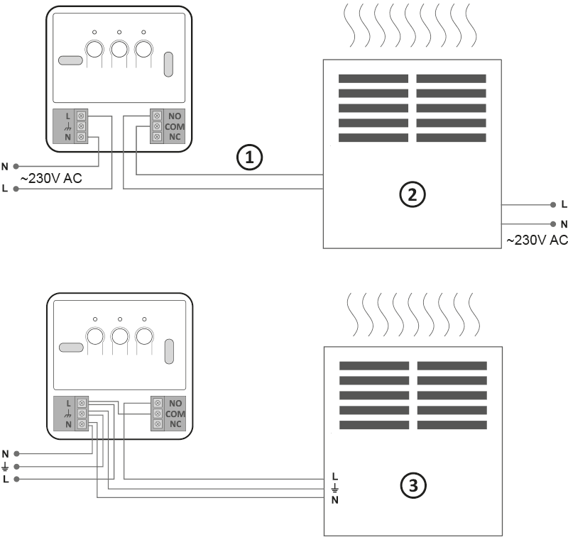
- Control
- Heating device, e.g. gas heater
- Electric heating device (MAX ~ 230 V, 16 A)
- Remove the cover from the front of the Auraton Heater Controller by unscrewing the screws to the half of their length.
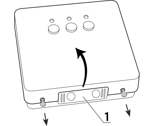
1 – end cap
- Connect the heating device to the terminals of the control device. Follow the operation and maintenance instructions of the heating device. The most commonly used are the terminals COM (common) and NO (normally open).
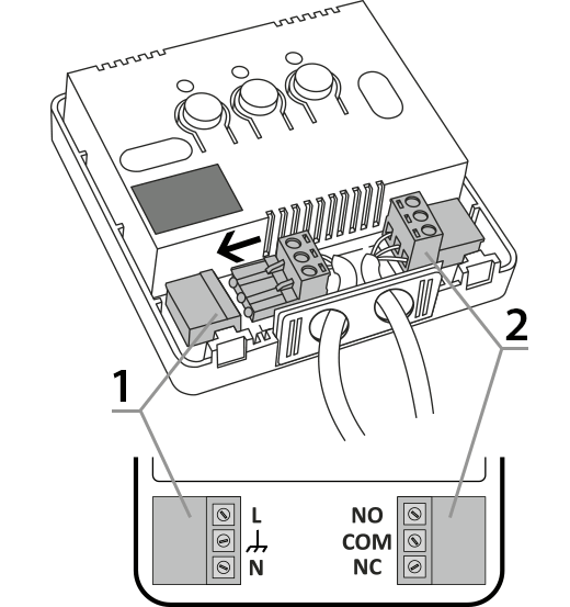
1 – power connector
2 – control connector - Connect the power supply cables to the terminals of the Auraton Heater Controller observing safety guidelines.
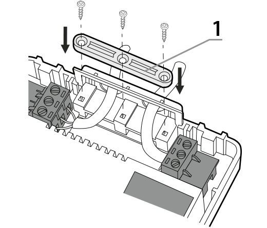
1 – cable fastener
- After connecting the cables, fix them with the “cable fastener” then replace the cover of the device.
Fixing to the wall
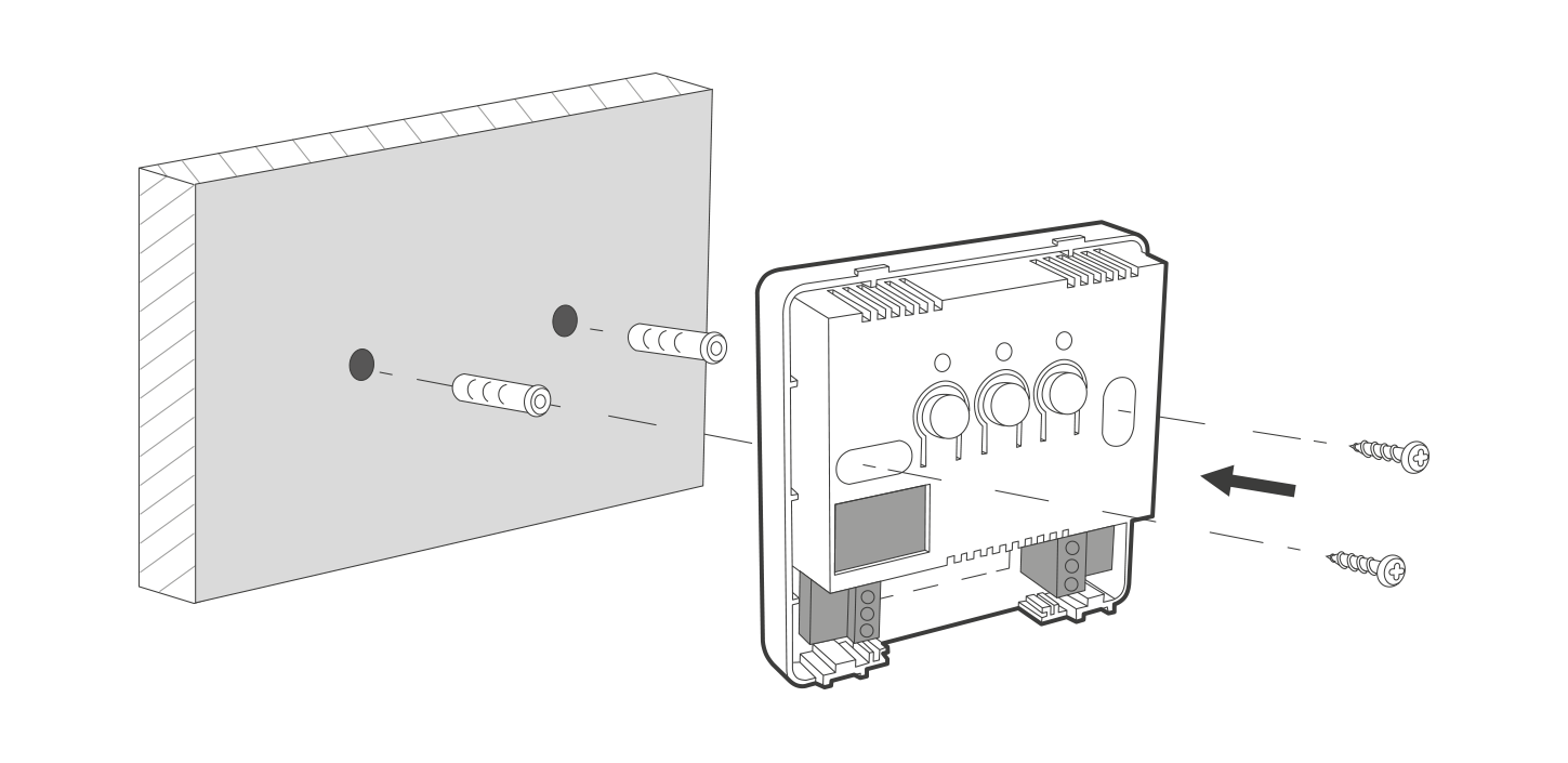
- Remove the front cover of the device.
- On the wall, mark the location of openings for the fastening screws.
- In the marked points drill holes having a diameter of dowels attached to the set (5 mm)
- Insert the dowels into the drilled holes.
- Fix Auraton Heater Controller with screws to the wall to ensure reliable fastening.
NOTE!If the wall is made of wood, there is no need to use dowels. Drill holes having a diameter of 2.7 mm instead of 5 mm and a screw-in the screws directly into the wood.
Pairing the devices
To ensure proper operation of Auraton Heater Controller, it is required to pair it with Auraton Heat Monitor or with Auraton Pulse.
After connecting to the network, turn on the receiver by a short press of the power button ( F ). When the device is activated, green LED of power supply will be lit and you will hear a single beep. To turn off the receiver, e.g. outside the heating season, press and hold the power button for 3 seconds until you hear a double beep and the green LED goes off – this indicates turning off the heating device.
- Pairing of Auraton Heater Controller is initiated by pressing and holding the right button for pairing (D) until the LED starts to flash in green, then release the button.
The device is waiting for paring for the period of 30 seconds. After this time, it automatically returns to normal operation. - Activate pairing mode of the other device to be added (examples described below).
- 3. When pairing is successfully completed, green LED on Auraton Heater Controller stops flashing, you hear a single beep and the devices starts its normal operation.
If an error occurs during pairing, repeat steps 1 and 2. In case of further errors, remove all paired devices from Auraton Heater Controller (see “Restoring factory settings”) and try again to pair the devices.
Activation of pairing – Heat Monitor
On Auraton Heat Monitor press simultaneously buttons b d or c d for 3 seconds until the transmission symbol ( W ) lights up on the display. Heat Auraton Monitor waits 30 seconds for pairing. After this time, it automatically returns to normal operation.
Activation of the pairing function – Auraton Pulse Central Unit
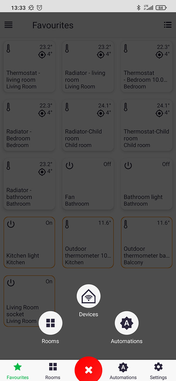
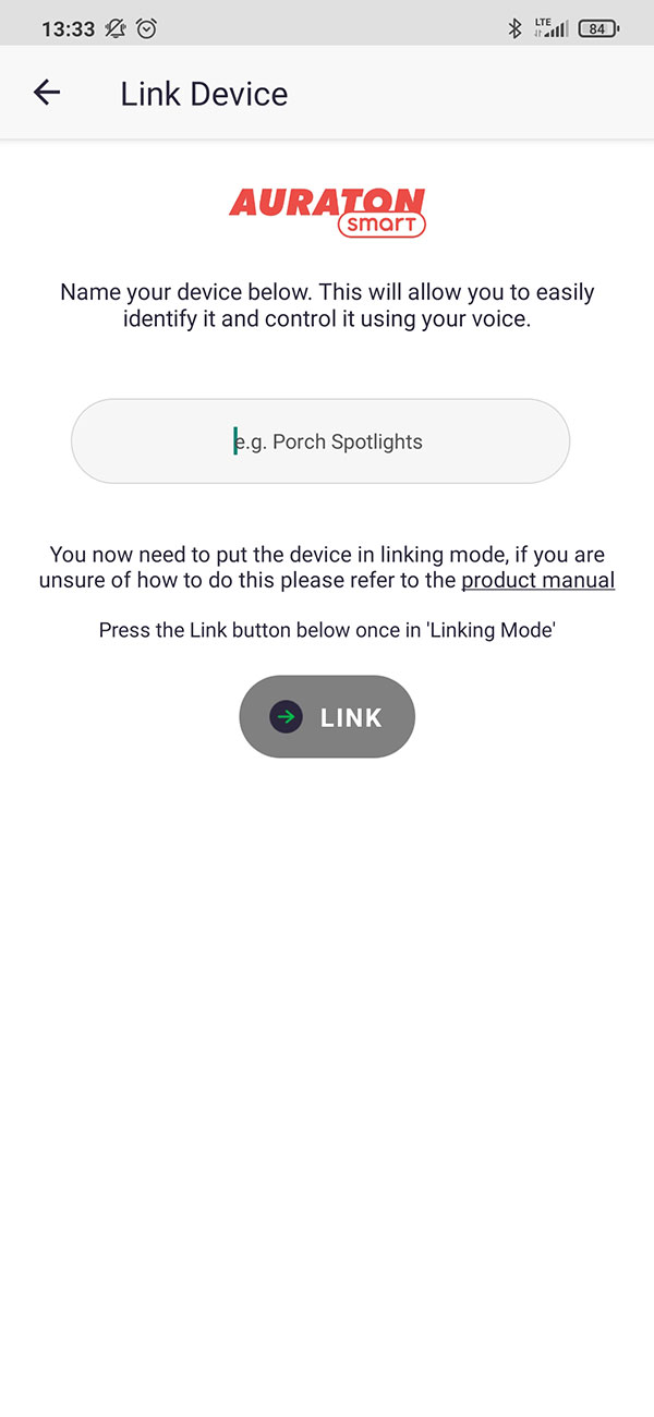
In Auraton Pulse, the pairing function is activated via Auraton Smart App. After it is enabled, press green ‘+’ button located on the centre of the screen. On the next screen, press the home icon marked as “Devices”. On the next screen, enter the name of the device that is added. After entering the name, press the “Add” button. After successful pairing, the device may be placed in any previously added room and added to ‘favourites’.
Restore factory settings
Deleting data of the devices paired with Auraton Heater Controller is initiated by pressing the left button out ( E ) and holding it for at least 10 seconds, until the LED stops flashing red, then release the button. Sound signals are the same as when pairing, i.e. pressing the button is signalled by a short beep, and after 10 seconds a double beep. This operation deletes all user data from the device, but the firmware version remains unchanged (it is not restored to the version valid at the purchase date).
Functions of the device
Principles of heating function
Auraton Heater Controller performs the function of heating in accordance with a hysteresis of 0.2 °C, i.e. when the target temperature is 21 °C, then the device will activate heating when the room temperature drops to 20.8 °C and it will turn off the heating when room temperature increases to 21.2 °C . The device is equipped with its own temperature sensor, but it is advisable to use an external temperature sensor, for example Auraton Heat Monitor.
Restoring previous firmware
Start from first disconnecting Auraton Heater Controller from the power supply, then press and hold the power button ( F ) and without releasing it connect the device again to the network. Wait for 3 flashes of green LED and release the button (all the LEDs should be OFF). Then, after device automatically restarts, the previous version of the firmware is restored (in the case of improper operation after the upgrade). The whole operation can take up to one minute, during which the unit must remain powered. Always the previous version of the firmware is loaded. When the firmware has been changed earlier from version 1.6 to 1.5, then the previous version is 1.6.
Signalling the working status
Each reception of radio-transmitted signal from a paired device is indicated by Auraton Heater Controller with a momentary alternation of LEDs colours. After activating the relay, LED is re and when the relay is switched off, LED is green.
Pressing any button is signalled by a short beep.
| D G |
Active green LED – the executive device is switched OFF (COM and NC contacts shorted). |
| E I |
Active red LED lights red – the executive device is switched ON (COM and NO contacts shorted). |
| D H |
LED flashes green – Auraton Heater Controller waits for device to be paired – (see section “Pairing the devices”). |
| E J |
LED flashes red – Auraton Heater Controller waits for confirmation of the procedure for restoring factory settings – (see section “Restoring factory settings”). |
| F | Active green LED of power supply – Auraton Heater Controller is turned ON. |
Device operational modes
Auraton Heat Monitor and Auraton Heater Controller can operate in two modes.
Mode I (local):
In this mode, the Heat Monitor and Heater Controller may work independently without the need to use Auraton Pulse central unit. Just correctly pair the controller with the boiler triggering device.
Mode II (remote):
In the remote mode, you can use Auraton Pulse web central unit, which provides the access to the entire system remotely from locations outside the home.
This allows you to remotely control heating, check battery levels, receive notifications about events, create schedules and more.
For proper remote control, you need access to the Internet both for the central panel and for the phone or tablet with the app (Android, iOS).
When using Mode II (remote), it is recommended to pair the Heater Controller with the Heat Monitor. Thanks to pairing the devices first, the set will work properly even in the event of a power outage. Up to 3 devices can be added to one Heat Monitor.
Operation with Auraton Pulse central unit
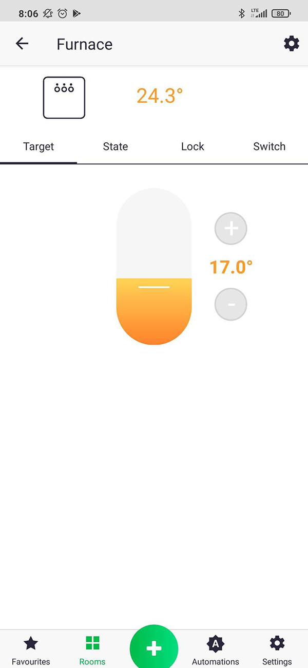
Auraton Heater Controller is paired with Auraton Pulse central unit and with other devices (as defined in the paragraph on pairing devices) and the only difference is that the pairing mode on the central unit is activated through the app by pressing green ‘+’ button at the bottom of the screen, which is followed by clicking the icon marked as “Devices”. Details are described in the user manual of the app. The picture below shows the screen for controlling the device in the app. It displays the following parameters: current temperature, target temperature, device status (ON/OFF), button lock (local control disabled), switch for direct control of the relay. The last three of these parameters can be changed in separate tabs, entered by pressing icons marked with relevant names.
Heater Controller thermostatic switch is primarily intended to cooperate with the Monitor Heat and Radiator Controller thermostatic head. In the application, you can easily link Auraton Heater Controller with Heat Monitor by creating two functions of “Group” type. One Group should include the current temperature, while the second Group the target temperature, to transfer each change in any device to other devices. If system is installed in a house, where the boiler is activated by Auraton Heater Controller, it is possible to link all mounted thermostatic heads with the boiler using the “Heating” function. This function activates the boiler, when the valve opening in any radiator with installed thermostatic head is higher than 0%. The “Heating” function may be also used when you have multiple controllers at home (without Radiator Controller thermostatic heads) and you want them to control the boiler. In this case, if any of the room with a thermostat is too cold, the heating will be activated.
Technical specifications
| Operating temperature range: | 0 – 45 °C |
| Temperature measurement range: | 0 – 45 °C |
| Temperature control range: | 0 – 40 °C |
| Additional features: | FrostGuard/Non-sparking switching contacts |
| The maximum load current of relay contacts: | 16A, 250V AC |
| Checking the operational status: | LEDs, sound signalling |
| Power supply: |
230 V AC ±10%, 50 Hz, 1.5 W |
| Compatible with Internet getaway | Auraton Pulse |
| Protection rating | IP20 |
| Radio frequency: | 868.150 MHz 868.450 MHz |
| Radio signal strength: | 11 dBm |
| Category of the radio receiver: | 2 |
| Operating range: | in a typical house, with standard wall structures – up to 30 m outdoors – up to 300 m |
Disposal of the device
O
The devices are marked with the crossed-out wheeled bin. According to European Directive 2012/19/EU and the Waste Electrical and Electronic Equipment Act, this kind of marking indicates that the equipment, after its operational life must not be disposed of together with other waste from households.
The user shall return it to a collection point for electrical and electronic waste.