User manual ver. 20250529
This document contains information on the safety, installation and use of the AURATON Heater Controller.
Basic information
The Auraton Heater Controller is a controller for a heating device, such as a furnace, and works with the AURATON Heat Monitor wireless regulator. The device is mounted next to the heating device and can operate under a load of up to 16A.
Device description
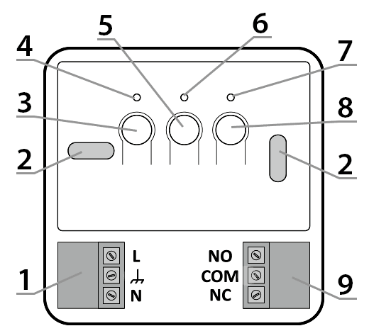
- – Detachable 230V power connector terminals
- – Mounting hole
- – On/Off button (F )
- – Green power LED
- – Factory Reset Button (E )
- – Red diode indicating that the actuator is switched on
- – Green LED indicating that the actuator is turned off
- – Device to device pairing button (D )
- – Control connector
Device assembly
P
WARNING: Before beginning installation, read this manual.
Failure to follow the instructions contained in this manual may be hazardous to your health and life and result in property damage. The manufacturer is not liable for any damage resulting from use inconsistent with this manual.
Q
WARNING! Electric shock hazard
. Before installing the AURATON Heater Controller, ensure that the power supply to the circuit to which the device is connected is disconnected. It is recommended that the installation be performed by a specialist.
Q
CAUTION! Disconnecting the power supply does not disconnect the output.
The Heater Controller is equipped with a bistable relay (self-retaining). This means that if the device's power supply is disconnected, the relay will remain in its last stored position. Please note that in such a case, dangerous voltage may be present on the terminals of the actuator connected to the Heater Controller. The NO and NC markings indicate the position of the contacts of the powered device when the heating device is off. Any changes to the device should be made with the power supply disconnected from both the Heater Controller and the actuator.
P
WARNING! Danger of damage to the electrical installation.
The device's power supply circuit must be equipped with a circuit breaker and overcurrent protection.
P
CAUTION! Danger of cable overloading.
The cables supplied with the controller are designed to carry a maximum load of 2.5A. If connecting devices with higher current consumption, they should be replaced with cables of appropriate cross-section.
For ease of installation, the connectors are equipped with removable terminals. Before making the cable connections, they can be disconnected from the controller. Wires can be routed from the bottom of the controller by breaking out the holes in the mounting plug, or from the rear of the controller if the wires are led out of the wall. To connect from the rear, break out the plug.
Method of connection to a heating device
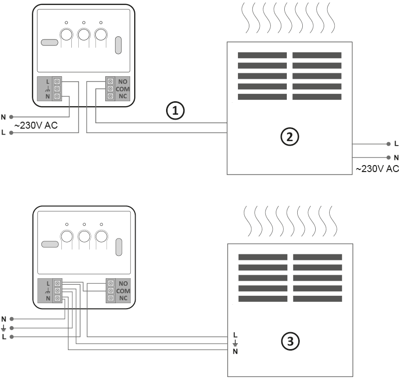
- Control
- A heating device , e.g. a gas furnace
- Electric heating device (MAX ~230 V, 16 A)
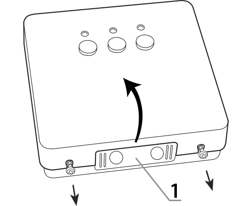
- Remove the front cover of the AURATON Heater Controller by unscrewing the screws halfway down.
1 – mounting plug - Connect the heating device to the device's control connector terminals. Follow the heating device's service manual. The most commonly used terminals are COM (common) and NO (normally open).
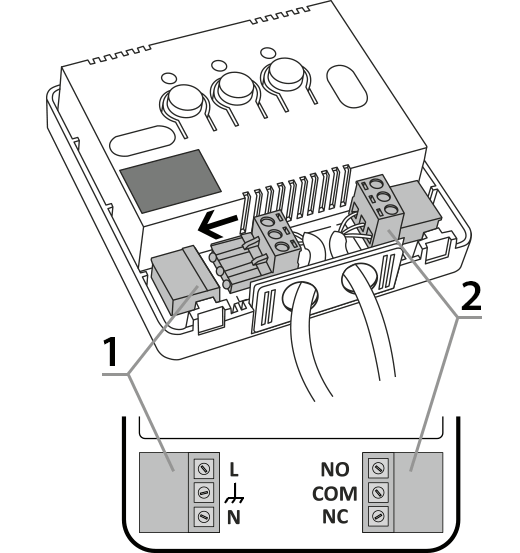
1 – power connector
2 – control connector - Connect the power cables to the AURATON Heater Controller power connector terminals while observing safety regulations.
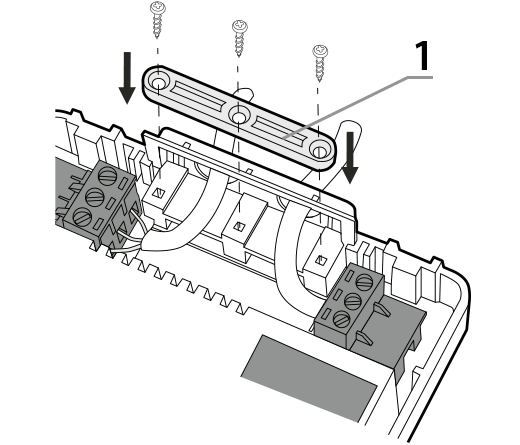
1 – cable mounting bracket - Once the cables are connected, secure them with the "cable retaining clip" and re-screw the cover onto the device.
Wall mounting
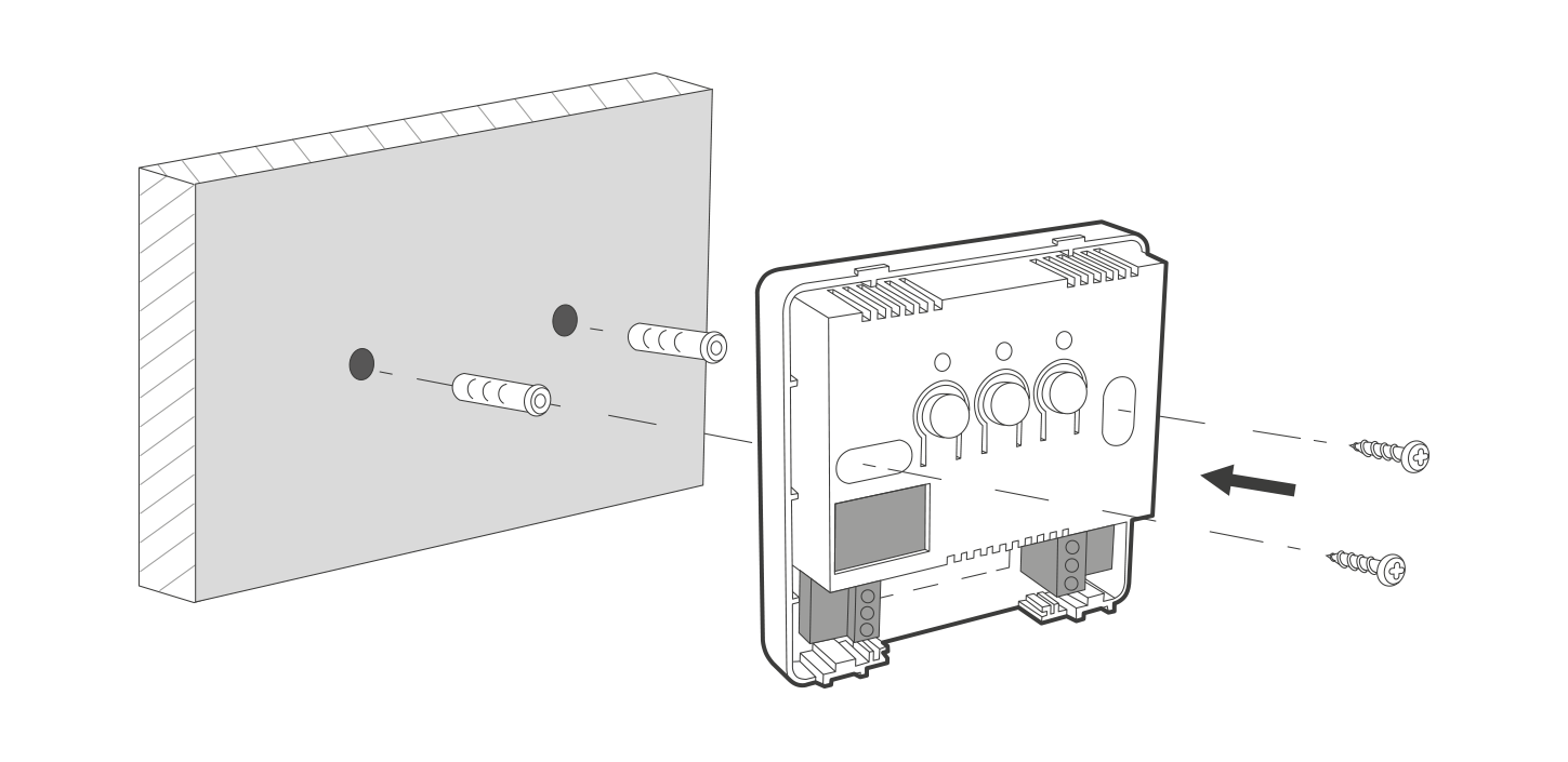
- Remove the cover from the front of the device
- Mark the position of the mounting screw holes on the wall.
- In the marked places, drill holes with the diameter of the dowels included in the kit (5mm)
- Insert expansion bolts into the drilled holes
- Screw the AURATON Heater Controller to the wall with screws so that they hold the device securely.
NOTE: If the wall is wooden, there is no need to use expansion bolts. Drill 2.7mm holes instead of 5mm and drive the screws directly into the wood.
Factory reset
To delete data from paired devices with the AURATON Heater Controller, first disconnect the power by unplugging it. Next, press and hold the center disconnect button (E ) and reconnect the power. Hold the button for at least 10 seconds until the LED stops flashing red, then release the button. The audio signal works the same way as pairing: pressing the button is indicated by a short beep, followed by a double beep after 10 seconds. This operation deletes all user data from the device, but the software version remains unchanged (it does not restore the version from the time of purchase).
The device paired with the AURATON Box gateway must also be removed from SUPLA Cloud.
Device functions
How does the heating function work?
The AURATON Heater Controller operates with a hysteresis of 0.2°C. For example, if the target temperature is 21°C, the device will turn on the heating when the room temperature drops to 20.8°C and turn it off when it rises to 21.2°C. The device is equipped with its own temperature sensor, but it is recommended to use an external temperature sensor, such as the AURATON Heat Monitor.
Function to restore the previous software
First, disconnect the AURATON Heater Controller from the power supply, press and hold the power button (F ), and then, while holding it, reconnect the device to the power supply. Wait for the green LED to flash three times and then release the button (all LEDs should be off). After the device automatically restarts, the previous software version will be restored (in the event of malfunctions after the update). The entire process may take up to a minute, and the device must remain powered on during this time . The previous software version is always loaded. If the software was previously updated from version 1.6 to 1.5, the previous version is 1.6.
Work signaling
Each time a radio transmission from a paired device is received, the AURATON Heater Controller signals this with a momentary alternating color change of the LEDs. When the relay is on, the LED is red; when the relay is off, the LED is green.
Pressing any button is signaled by a short beep.
| D G |
The diode is green – the actuator is turned off (COM and NC contacts closed). |
| E I |
The diode lights red – the actuator is switched on (COM and NO contacts closed). |
| D H |
The diode flashes green – AURATON Heater Controller is waiting for the device to be paired – ( chapter: “Pairing devices” ). |
| E J |
The LED flashes red – the AURATON Heater Controller is waiting for confirmation of the factory settings restoration procedure – ( chapter: "Restoring factory settings" ). |
| F | Green power LED – AURATON Heater Controller is on. |
Device operating modes
The AURATON Heat Monitor and AURATON Heater Controller set can operate in two modes.
Mode I (Local):
In this mode, the Heat Monitor and Heater Controller can operate independently without the need for an AURATON Box internet gateway. The regulator must be properly paired with the furnace controller.
Mode II (remote):
In remote mode, you can use the AURATON Box internet gateway, allowing you to access the entire system from outside your home.
This allows you to remotely control your heating, check battery charge levels, receive notifications about potential events, create schedules, and much more.
For proper remote operation, Internet access is required both from the gateway itself and from a phone or tablet with the application (Android, iOS).
When using Mode II (remote), it is recommended to first pair the Heater Controller with the Heat Monitor. This pairing will ensure the set will work properly even if the Auratron Box itself is powered down.
Radio connection failure indication
If the radio connection is lost for more than one hour, the device will display a fault indication (LEDs flash alternately red and green).
The fault indication is displayed alternately with the current readings every 5 seconds.
Until the problem is resolved, the device will maintain the temperature setpoint according to its built-in temperature sensor (the last setpoint value will be retained). When the radio connection is restored, the error is cleared and the AURATON Heater Controller returns to normal operation.
Radio signal test
The AURATON Heater Controller is equipped with a radio signal tester. To enable this function:
- Press the two outermost buttons (F ) and (D ). Activation of the function is signaled by the appropriate number of LEDs flashing. If there is no radio signal, the LEDs will remain off.
- Flashing only one left LED indicates insufficient radio signal strength, which may cause communication problems. If both the left and middle LEDs flash, the radio signal strength should be sufficient for normal operation. Flashing all three LEDs indicates excellent signal strength. The radio signal tester mode lasts for 20 seconds, after which the controller will display the current readings.
- To turn off the tester function faster, press any button for at least 1 second.
The activated test mode does not affect the heating control process.
Power failure mode
In the event of a power outage and the device being turned on again, the AURATON Heater Controller remains in the position it was in before the power loss until it receives information from the paired device (AURATON Heat Monitor regulator, AURATON Box gateway).
Device pairing
AURATON Heater Controller, for correct operation, must be paired with the AURATON Heat Monitor regulator or the AURATON Box gateway.
If you have a simple configuration: AURATON Box gateway + AURATON Heat Monitor regulator + AURATON Heater Controller – even if you plan to control the devices only using the SUPLA app, it is recommended to perform two-way pairing of AURATON devices.
-
First, pair your devices directly with each other – this will provide a backup form of communication in case the app crashes or there is no internet access.
-
Then pair the devices with the AURATON Box gateway to enable remote control via the SUPLA application on your phone, tablet or computer.
After connecting to the mains, turn on the controller by briefly pressing the power button (F ). When the device is turned on, the green power LED will illuminate and a single beep will sound. To turn off the controller, e.g., outside the heating season, hold the power button for 3 seconds until a double beep is heard and the green power LED turns off, thus turning off the heating device.
- Pairing the AURATON Heater Controller is initiated by pressing and holding the right pairing button (D ) until the LED flashes green, at which point you can release the button.
The device waits 30 seconds for pairing. After this time, it will automatically return to normal operation. - Turn on pairing mode on the second device you want to add (examples described below).
- Successful completion of pairing is indicated by the LED on the AURATON Heater Controller stopping flashing green, a single sound signal and transition to normal operation.
If an error occurs during pairing, repeat steps 1 and 2. If further errors occur, deregister all devices from the AURATON Heater Controller (see "Restoring factory settings") and try pairing the devices again.
Enabling steaming – Heat Monitor controller
On the AURATON Heat Monitor controller, press theb d orc d for 3 seconds until the transmission symbol (W ) lights up on the display. The AURATON Heat Monitor controller waits 30 seconds for pairing. After this time, it will automatically return to normal operation.
Enabling pairing – AURATON Box gateway
Pairing the AURATON Heater Controller with the AURATON Box gateway can be done in two ways:
- On the AURATON Box gateway, briefly press the right "Auraton" pairing button (
 ) – the LED under the button will start flashing. Then, put the controller into pairing mode.
or
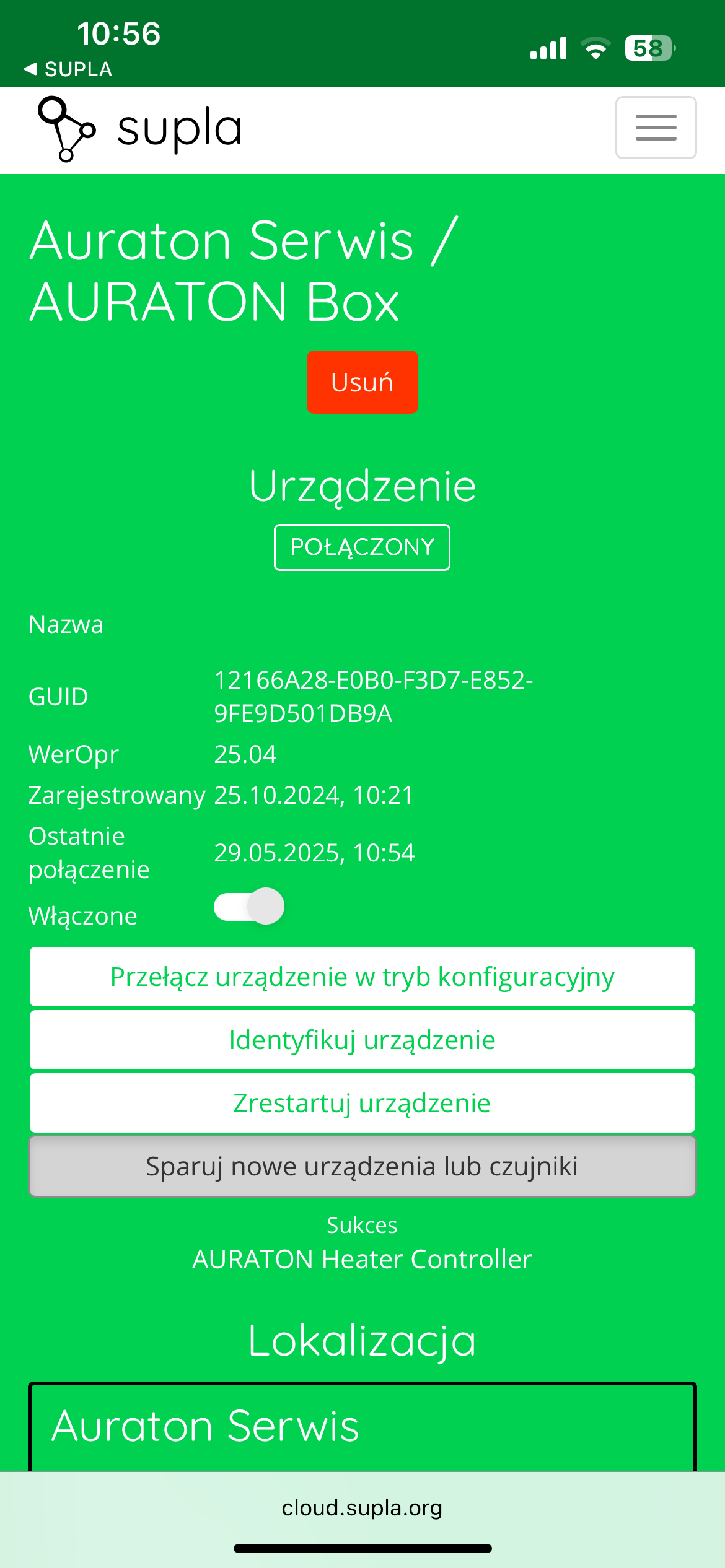
- In Supla Cloud, enter the AURATON Box gateway channel and press the "Pair new devices or sensors" button – the LED under the right "Auraton" pairing button will start flashing. Then, put the controller into pairing mode.
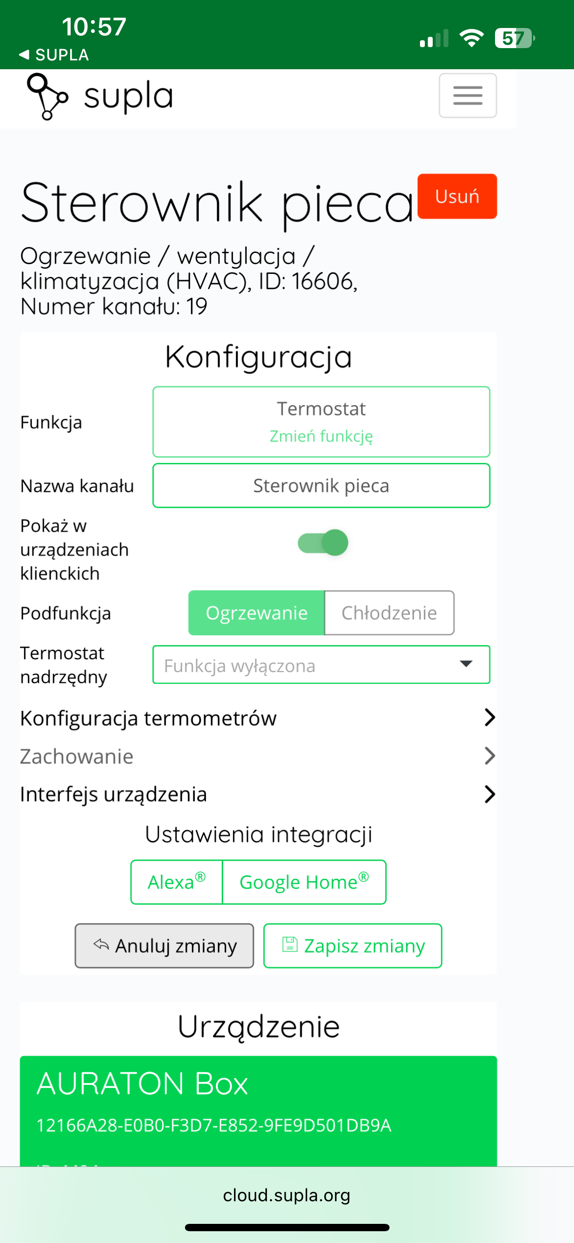
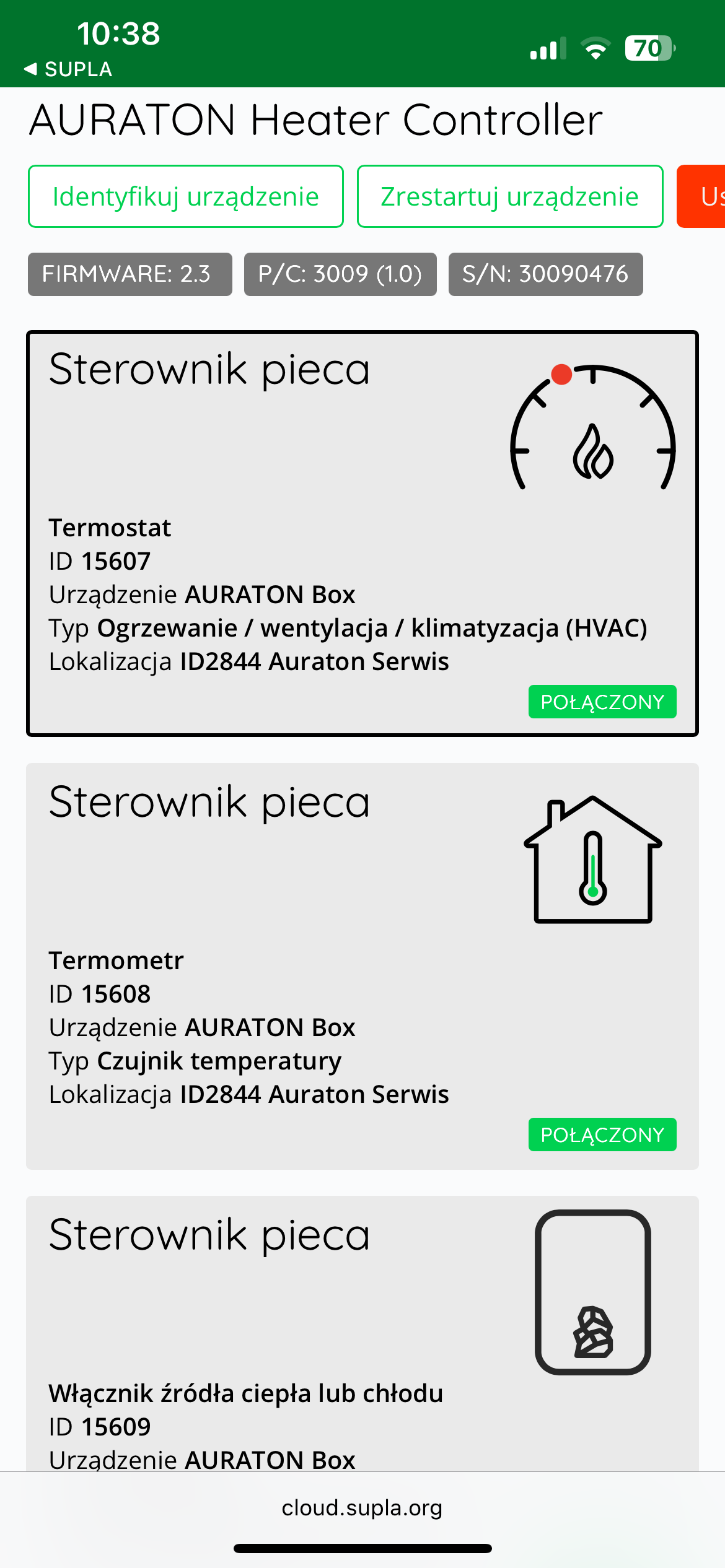
After pairing the AURATON Heater Controller with the Auraton Box gateway, it is recommended to immediately assign a name (e.g., "Furnace Controller" ) to the controller in all three of its channels (thermostat, thermometer, and heat or cooling switch) in Supla Cloud. By default, the device is named according to the model, e.g., "Heater Controller," which can be confusing when using multiple devices of the same type. To facilitate identification, it is a good idea to give the controller a unique name immediately after pairing. To do this, edit the "Channel Name" and confirm the changes by clicking " Save Changes ." Repeat this process for all channels assigned to the device in Supla Cloud .
Cooperation with the SUPLA application
Cooperation of the AURATON Heater Controller with the AURATON Heat Monitor temperature controller in the SUPLA application
Goal: We have a simple smart home system consisting of a single central AURATON Heat Monitor controller and an AURATON Heater Controller. We want the controller to control the device that turns on the heating in the home. When the current temperature on the AURATON Heat Monitor controller drops below the target temperature by the hysteresis value, the AURATON Heater Controller will turn on the furnace. When the current temperature on the controller exceeds the target temperature by the hysteresis value, the controller will turn off the furnace.
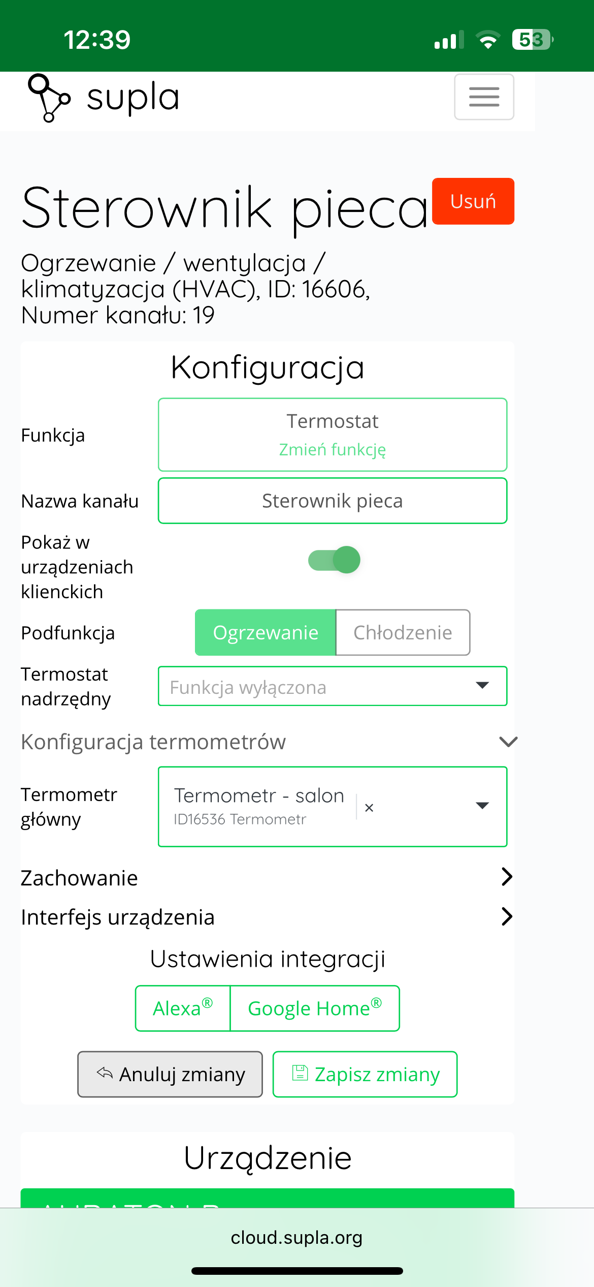
Solution: In the Supla app, select " Supla Cloud " from the menu and log in. Then, enter the AURATON Box gateway channel. Then, enter the heating device controller's thermostat channel (e.g., "Furnace controller"). In the "Thermometer configuration" , select our central temperature controller (e.g., "Temperature controller" as the "Main thermometer." select the same temperature controller as the " Master thermostat
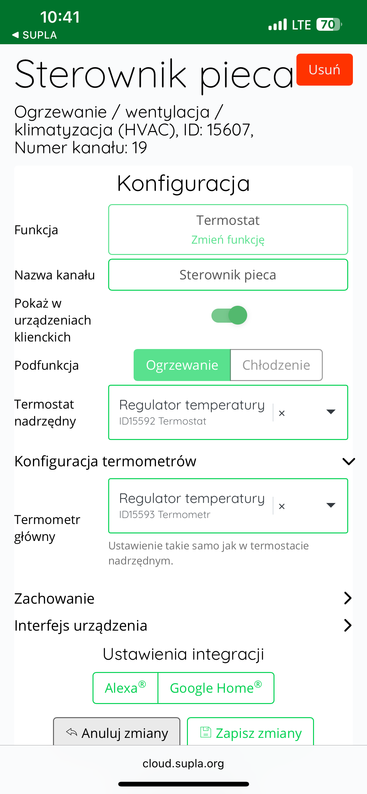
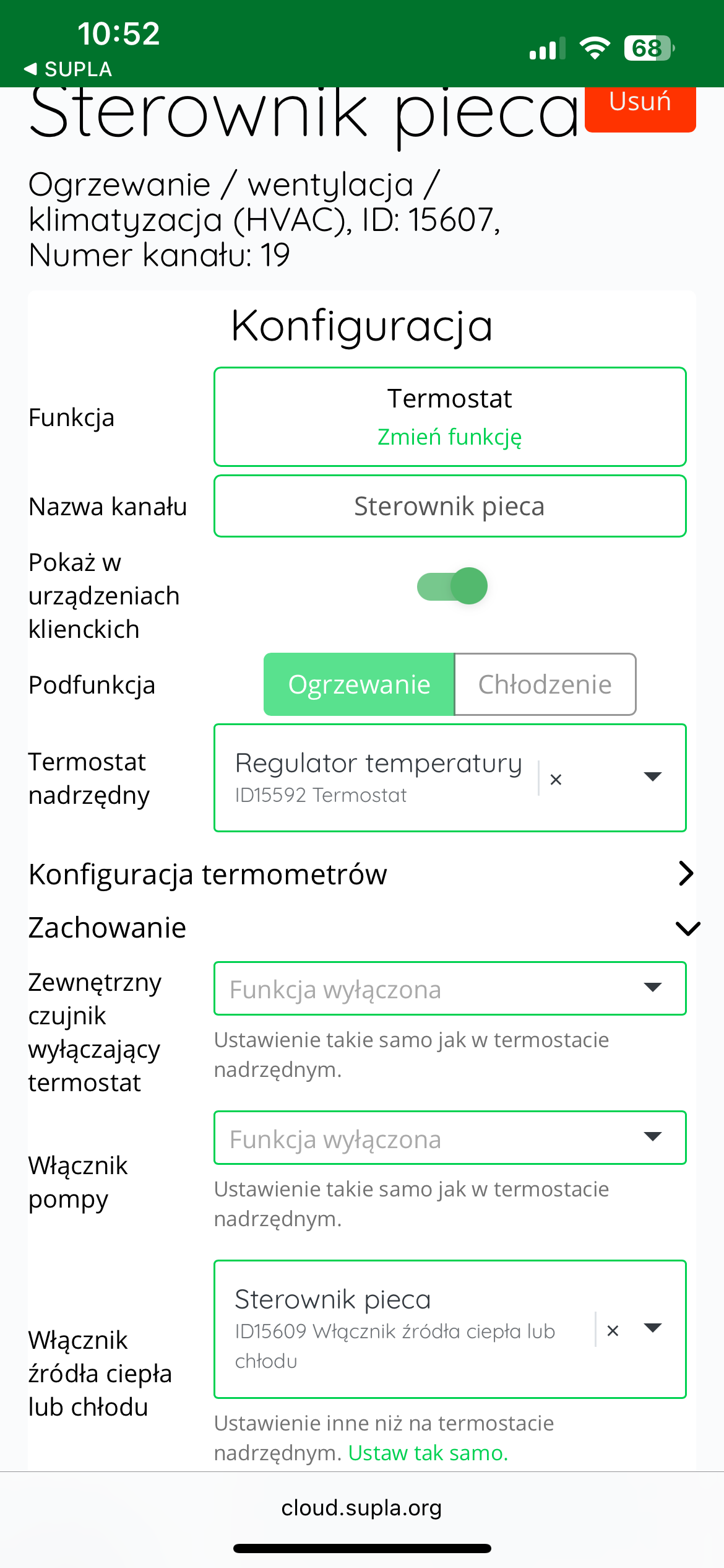
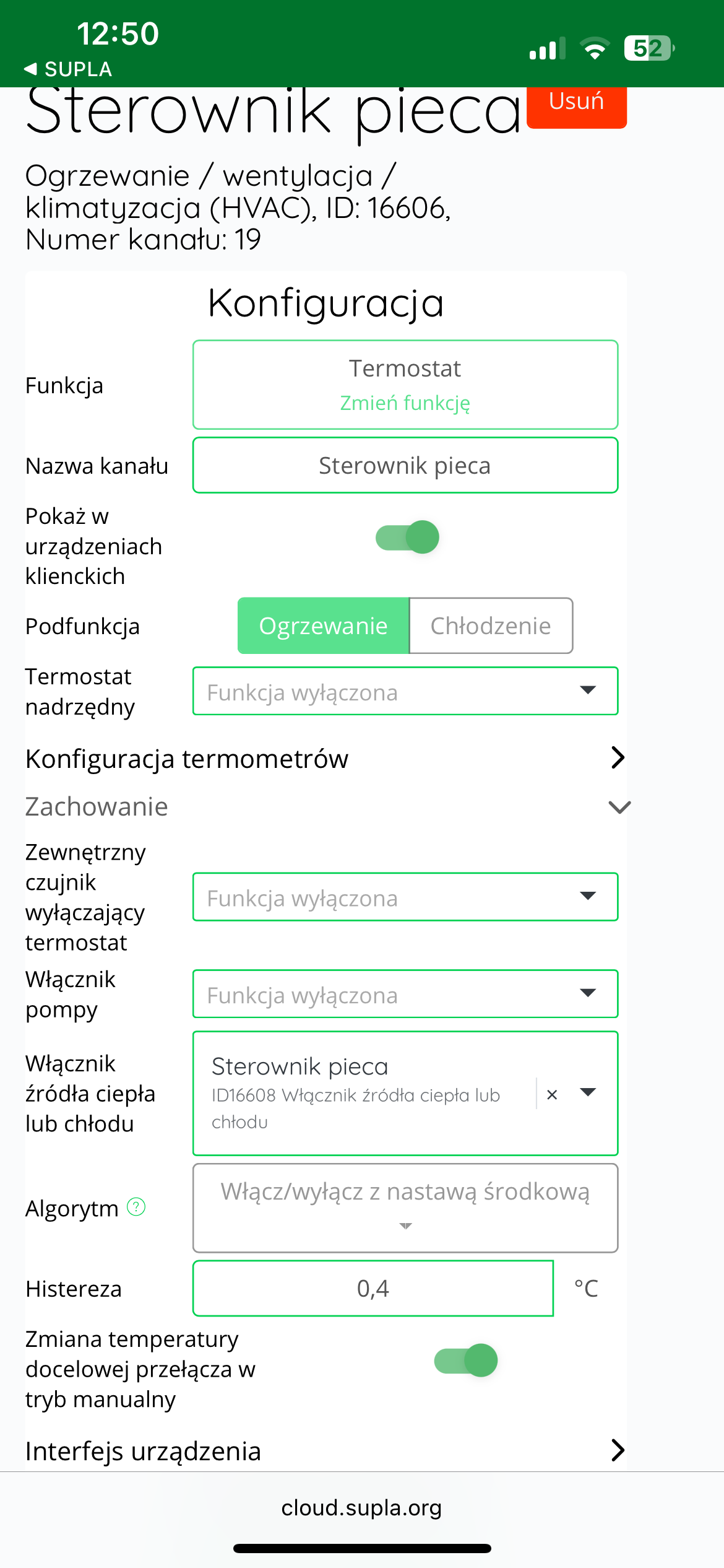
Additionally, in the "Behavior" , in the "Heating or cooling source switch" , select the device that will turn on the heating, i.e., the AURATON Heater Controller, here called "Furnace controller." Finally, save everything by pressing the " Save changes" button.
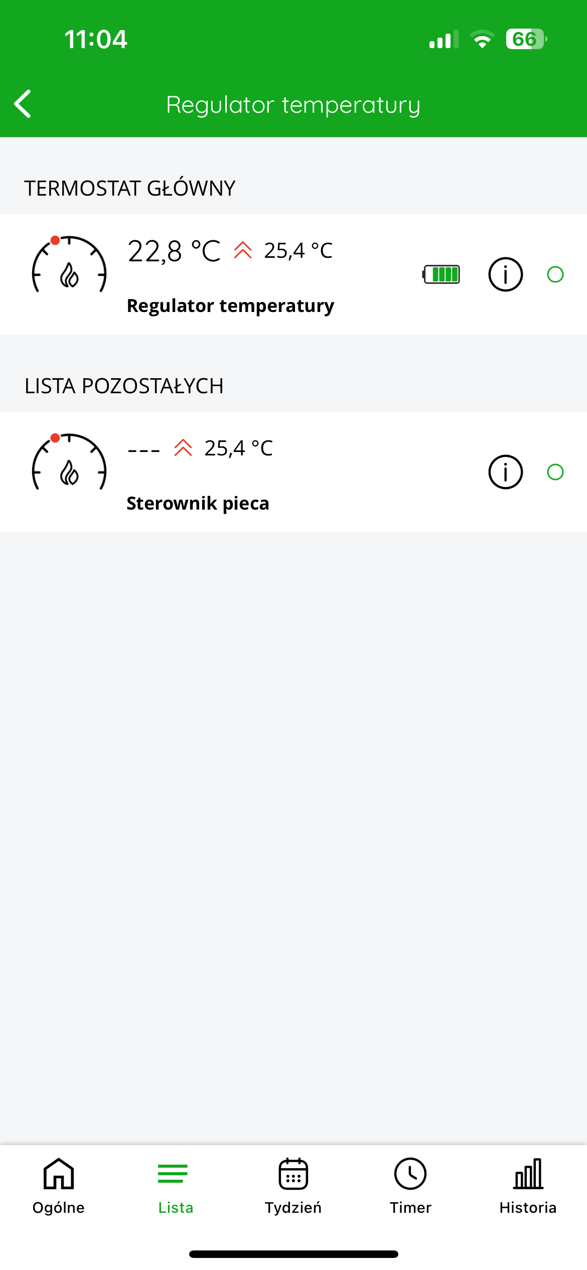
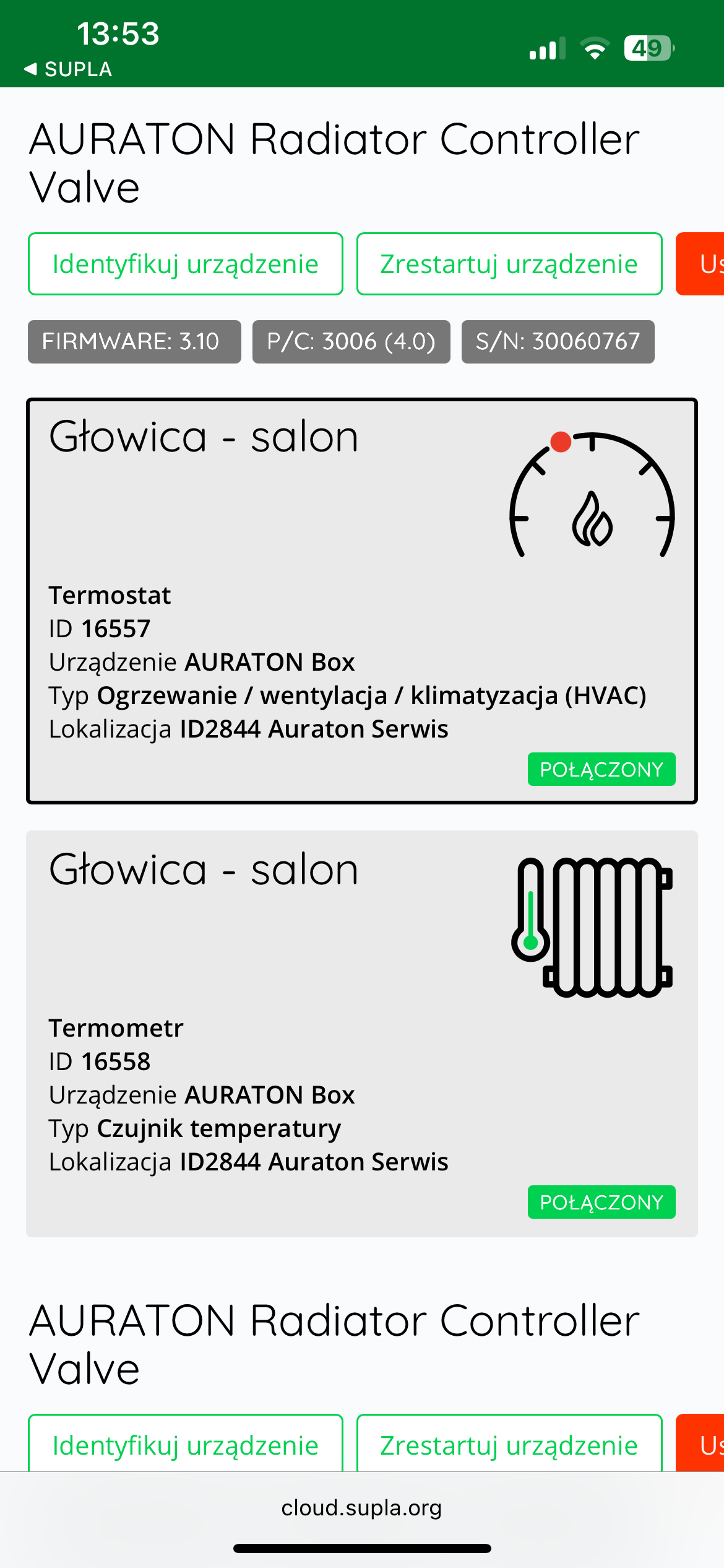
In the application, after entering the temperature controller, an additional "List" tab will appear at the bottom of the screen, after clicking on which you can see which devices are connected to each other.
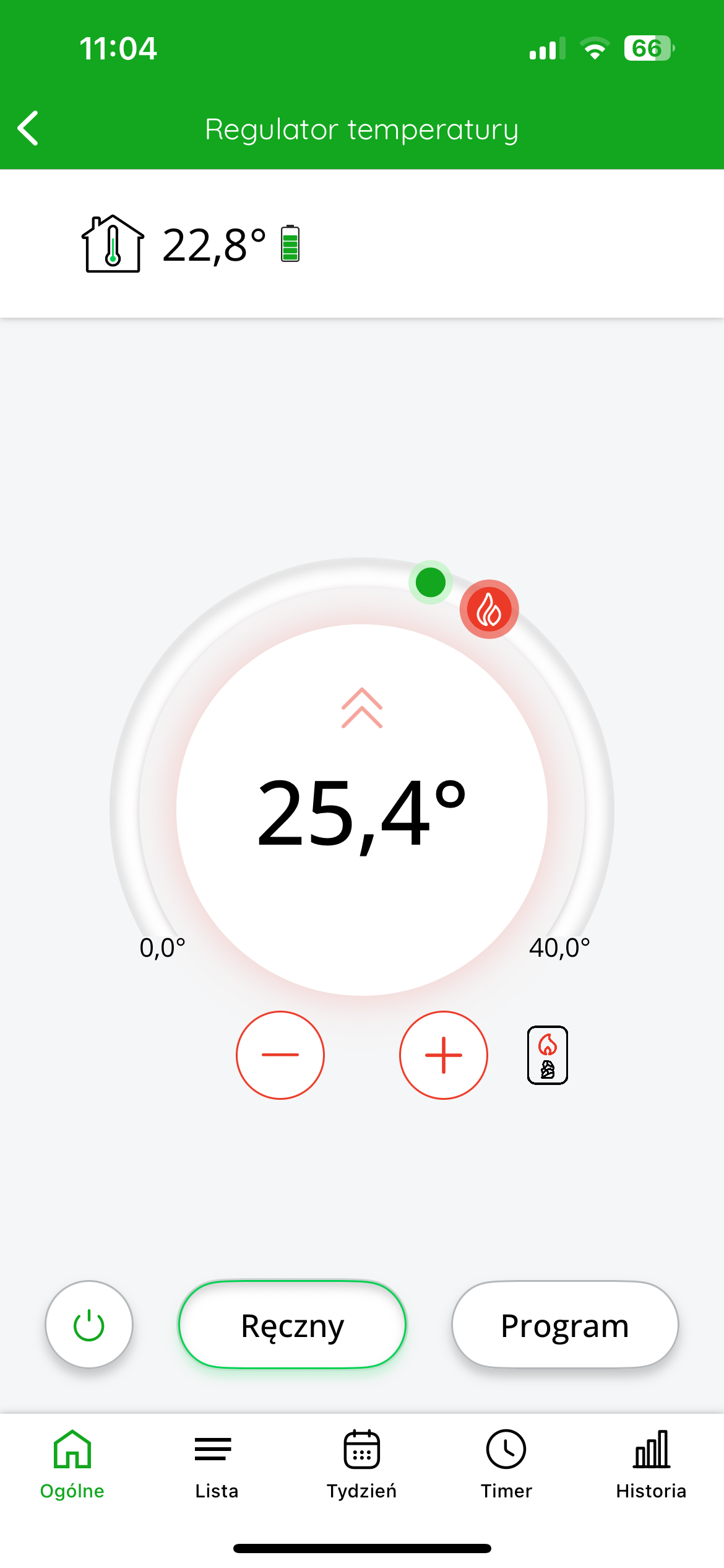
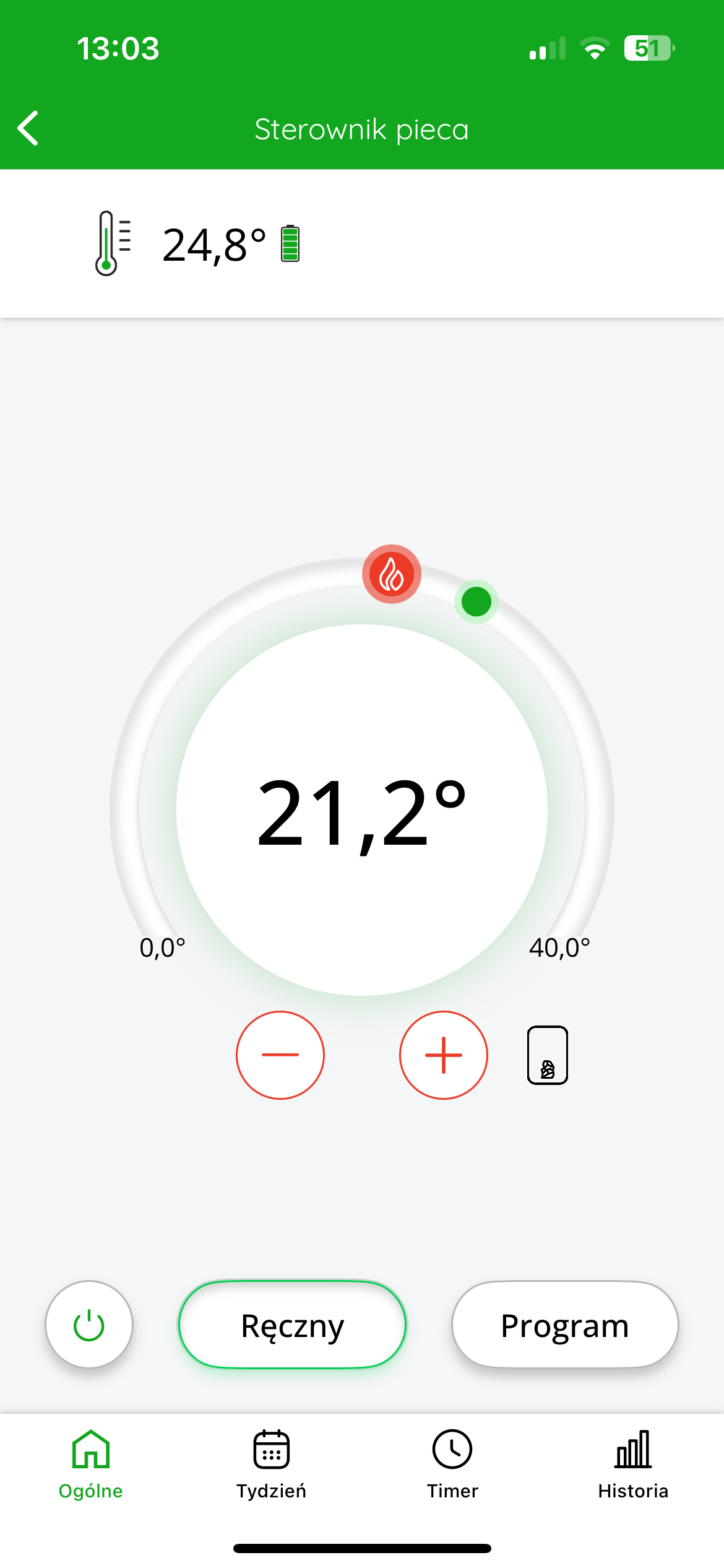
The top left of the display shows the temperature measured by the controller. The target temperature is displayed in the center of the screen.
You can roughly adjust the target temperature by moving the red slider. For more precise settings, use the "+" or "-" buttons.
Cooperation of the AURATON Heater Controller with the AURATON Temperature Sensor Indoor thermometer in the SUPLA application
Goal: We have a simple smart home system consisting of an AURATON Temperature Sensor Indoor thermometer and an AURATON Heater Controller. We want the current (measured) temperature, based on which the controller turns the home's heating on and off, to be derived from the AURATON Temperature Sensor Indoor thermometer. When the current temperature on the AURATON Temperature Sensor Indoor thermometer drops below the target temperature by the hysteresis value, the AURATON Heater Controller will turn on the furnace. When the current temperature on the controller exceeds the target temperature by the hysteresis value, the controller will turn off the furnace.
Solution: In the Supla app, select " Supla Cloud " from the menu and log in. Then, enter the AURATON Box gateway channel. Then, enter the heating device controller's thermostat channel (e.g., "Furnace controller"). In the "Thermometer configuration" , select your thermometer as the "Main thermometer" (e.g., "Thermometer – living room").
Additionally, in the "Behavior" , in the "Heating or cooling source switch" , select the device that will turn on the heating, i.e., the AURATON Heater Controller, here called "Furnace controller." Finally, save everything by pressing the " Save changes" .
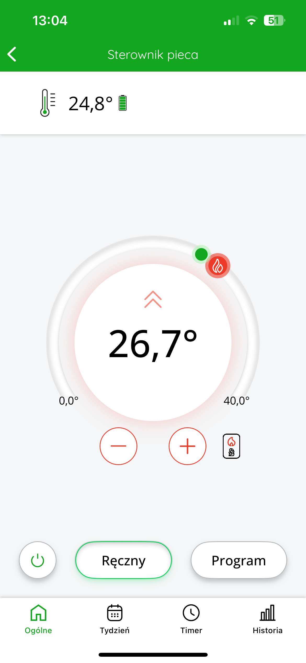
In the SUPLA app, the temperature measured by the thermometer is displayed at the top left of the screen. The target temperature is displayed in the center of the screen.
You can roughly adjust the target temperature by moving the red slider. For more precise settings, use the "+" or "-" buttons.
Cooperation of the AURATON Heater Controller with the AURATON Radiator Controller head in the SUPLA application
If you have a radiator heating system and use the AURATON Heater Controller to switch on the furnace, it is possible to link all installed AURATON Radiator Controller heads with this controller to enable automatic control of the heat source.
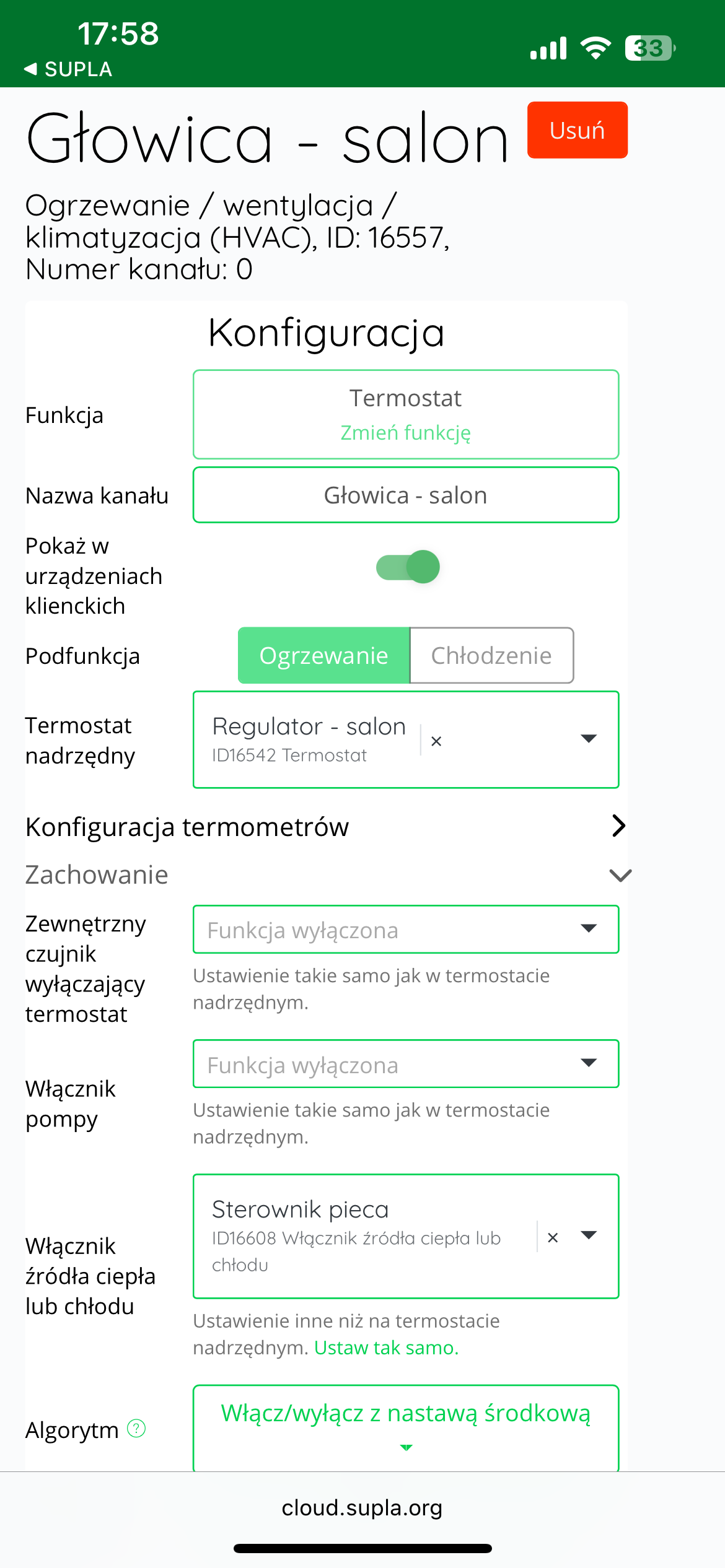
To configure cooperation between the radiator heads and the controller, log in to Supla Cloud and go to the AURATON Box gateway channel . Then, enter the radiator head's thermostat channel , for example, "Head – Living Room."
Next, expand the "Behavior" and in the "Heating or cooling source switch" , select the device that is responsible for turning on the furnace - usually it will be "Furnace controller" or "Heater Controller".
After making your selection, click the "Save changes" to confirm your settings.
This operation must be repeated for each AURATON Radiator Controller radiator head that we want to associate with the furnace controller.
From this point on, whenever any of the heads requests heat, the AURATON Heater Controller will start the furnace. The furnace will operate until the set temperature in the given room is reached.
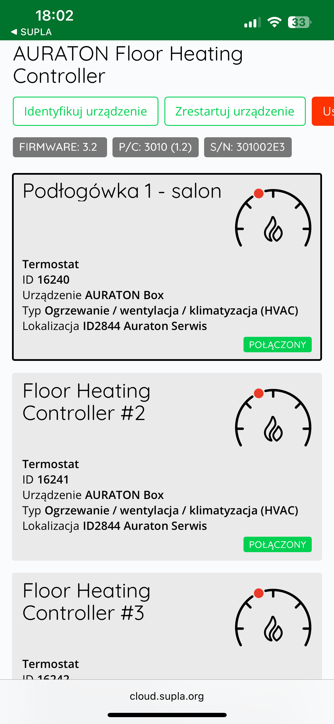
Cooperation of the AURATON Heater Controller with the zone(s) of the AURATON Floor Heating Controller wireless underfloor heating strip in the SUPLA application
If you have underfloor heating and you need to control the operation of the heater, but there is no possibility of connecting the strip to the heater by wire, the control function can be taken over by the AURATON Heater Controller.
To configure such cooperation in the SUPLA system, log in to the Supla Cloud and then enter the AURATON Box gateway channel .
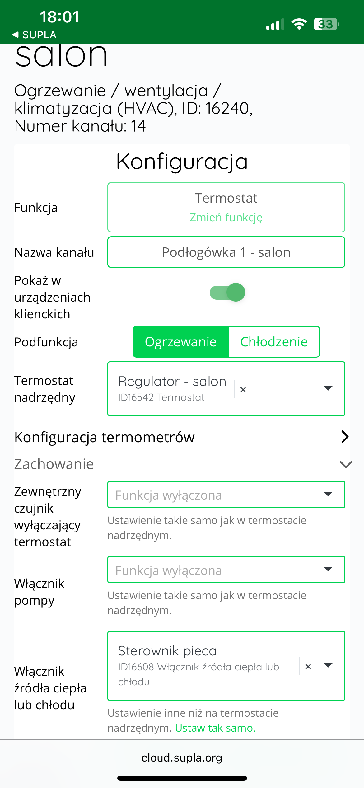
In the next step, enter the channel corresponding to the thermostat of the selected zone of the AURATON Floor Heating Controller strip , for example named "Floor 1 - living room" .
After entering the channel, expand the "Behavior" , and then in the "Heating or cooling source switch" , select the device responsible for switching on the furnace, i.e. the AURATON Heater Controller , which may be marked as " Furnace controller ".
After making your selection, confirm the settings by clicking the "Save changes" .
The same procedure should be repeated for each subsequent underfloor heating zone that we want to link to the furnace controller.
Once the configuration is complete, the system will operate in such a way that when any zone reports a demand for heat, the AURATON Heater Controller will start the furnace.
The furnace will operate until the temperature in a given room reaches the set point in the thermostat settings.
Standalone operation of the AURATON Heater Controller
The AURATON Heater Controller can operate as a standalone device, without the need to assign additional temperature sensors or controllers. When combined with the AURATON Box gateway, it creates a complete and autonomous heating control system.
The device has:
-
internal temperature sensor – enables current measurement of the ambient temperature,
-
thermostat – responsible for maintaining the set temperature,
-
relay – controls the operation of the heating device (e.g. boiler, heater, heating mat), turning it on or off according to the heat demand.
Thanks to these functions, the AURATON Heater Controller can be used as a single heating control point in rooms where there is no need to use additional system components.
Examples of applications:
-
Production hall – the device can be mounted on a pole or wall. It measures the ambient temperature and turns on the heater when the temperature drops below a preset value.
-
Workshop or garage – where we want to maintain a constant temperature without the need for additional automation.
-
Technical or utility rooms – where simplicity and efficiency of operation are important (e.g. controlling a heater, fan heater or storage heater).
-
Summer houses and gazebos – as a simple protection against freezing, without the need for an extensive installation.
-
Office and storage containers – enabling temperature control in places of temporary use.
With this type of use, the device is ready to work immediately after pairing it with the AURATON Box gateway – it does not require any configuration in SUPLA Cloud.
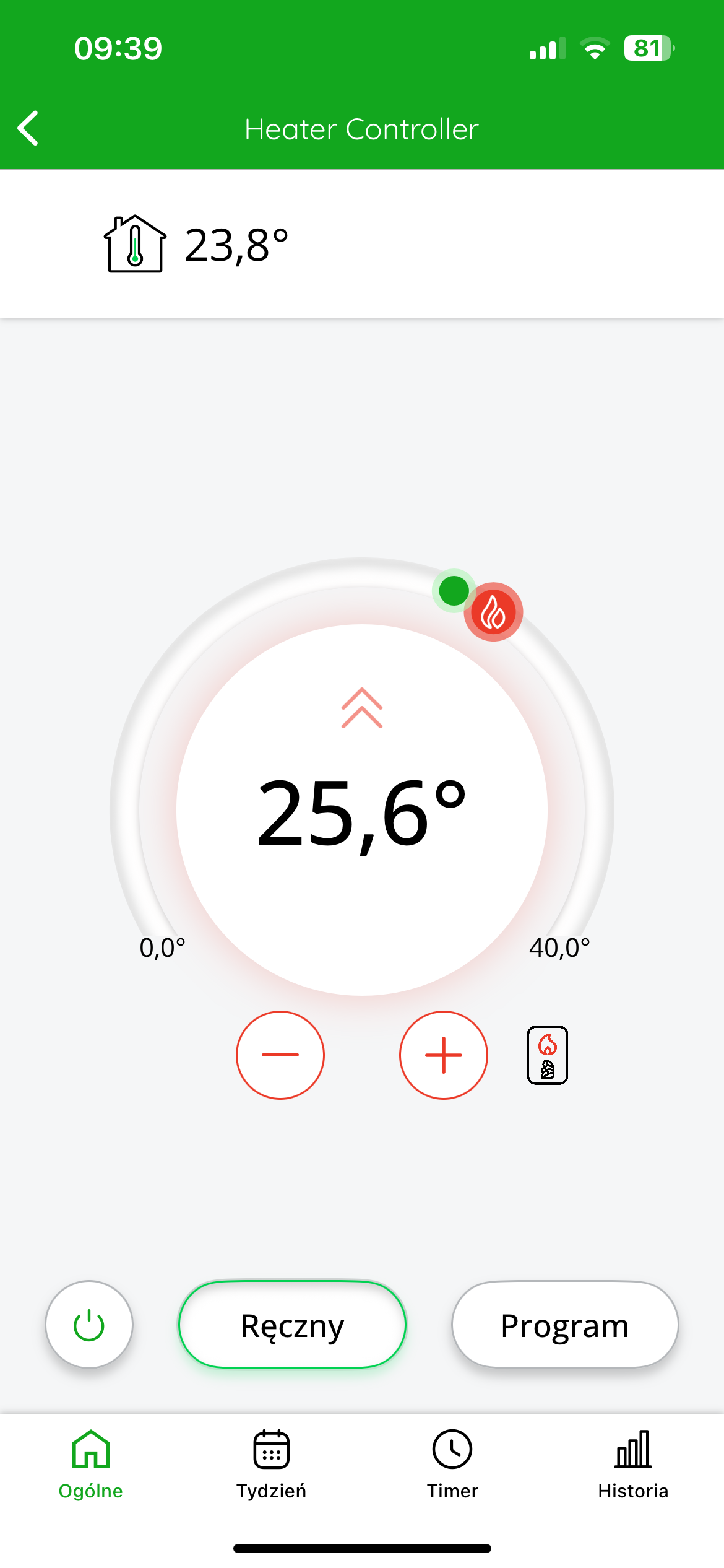
In the app, the temperature measured by the controller is displayed at the top left of the screen. The target temperature is displayed in the center of the screen.
You can roughly adjust the target temperature by moving the red slider. For more precise settings, use the "+" or "-" buttons.
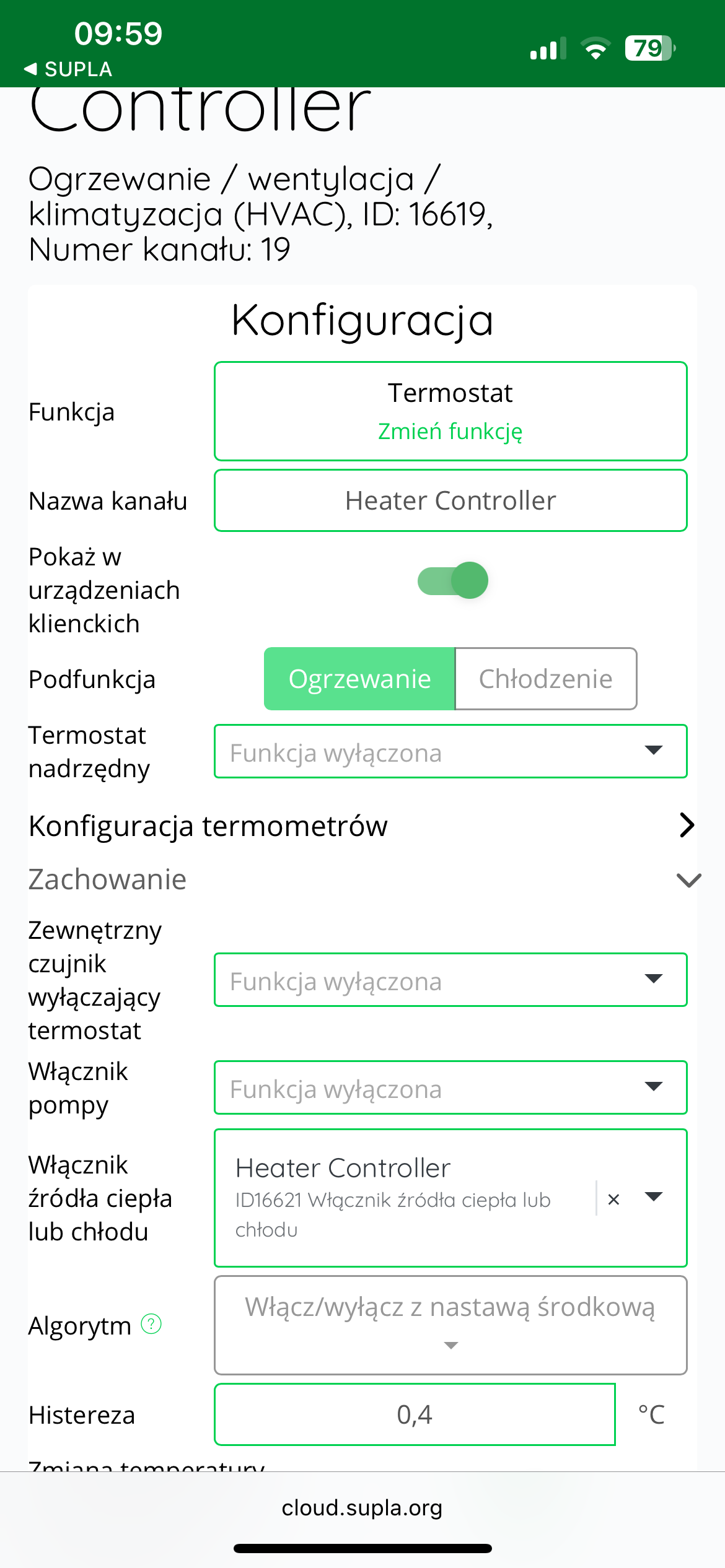
Other configuration settings in SUPLA Cloud
Hysteresis value
The factory hysteresis value is set to 0.4 (+/- 0.2°C). You can edit it in Supla Cloud, in the thermostat channel, in the "Behavior" – "Hysteresis" in the range 0.2 – 2 (+/- 0.1°C – +/- 1°C). After making the change, click the "Save changes" button.
For correct operation, the hysteresis value in the AURATON Heater Controller should match the hysteresis value in the AURATON Heat Monitor controller.
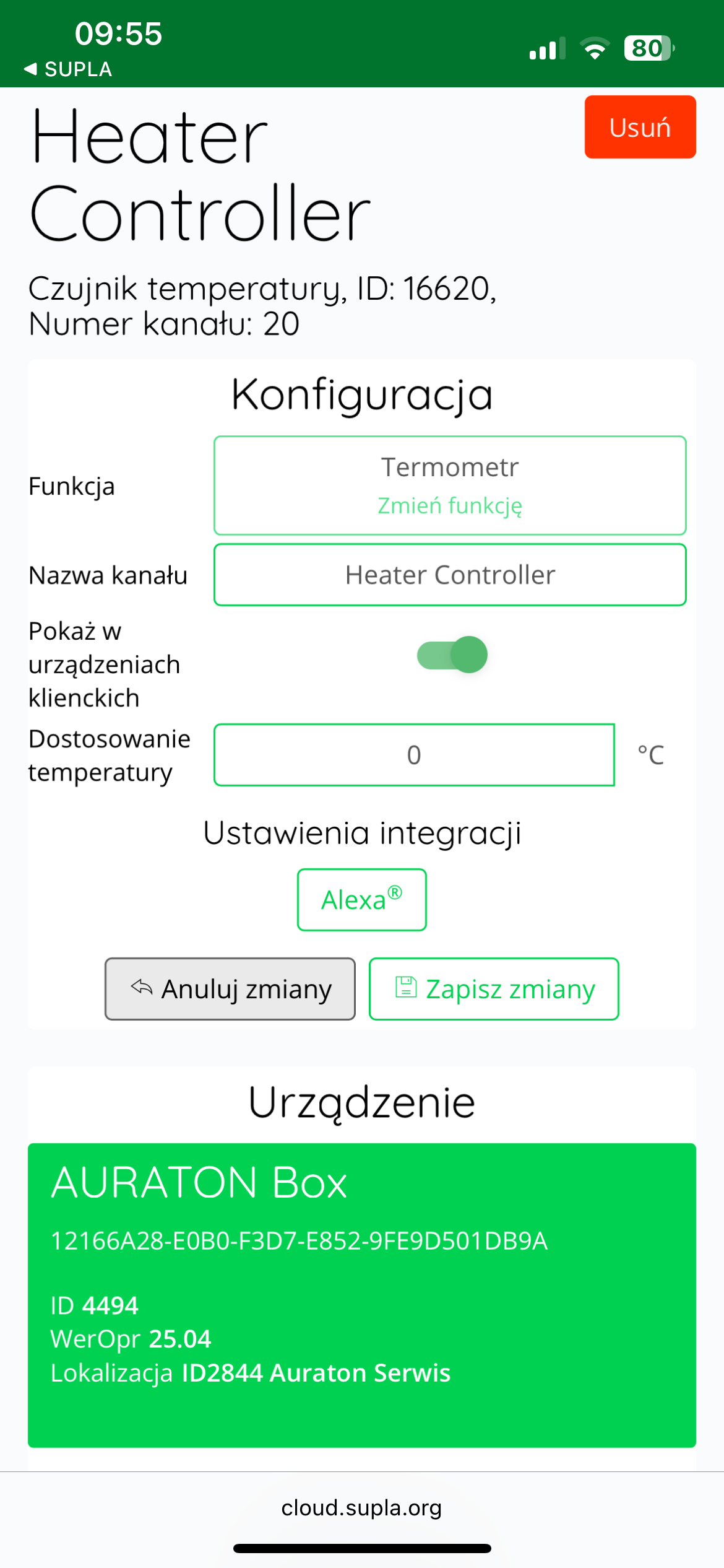
Calibration of temperature readings
If the temperature read by the internal sensor of the AURATON Heater Controller differs from the actual temperature in the room, the user can calibrate the temperature readings .
To adjust the reading, log in to SUPLA Cloud and then go to the AURATON Box gateway channel .
The next step is to enter the thermometer channel of the AURATON Heater Controller.
In the "Temperature Adjustment" , the user can enter a correction value between -3.0°C and +3.0°C , with an accuracy of 0.1°C . A positive value will raise the displayed temperature, while a negative value will lower it.
After making the appropriate correction, click the "Save changes" to confirm the setting.
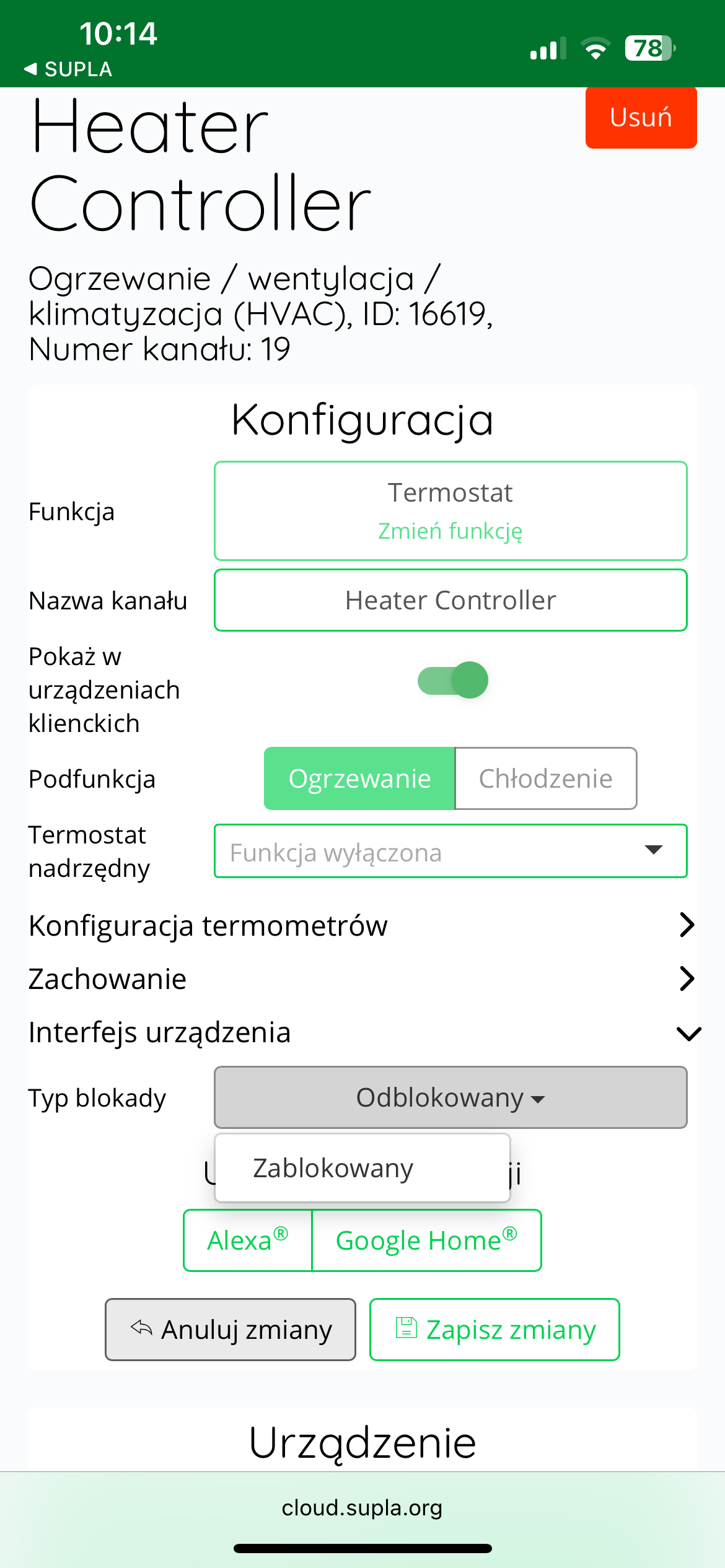
Button lock
SUPLA Cloud allows you to completely lock the device's buttons to prevent unauthorized access. This feature can be enabled in the thermostat channel, in the "Device Interface" tab. , select "Locked" in the "Lock Type" Save the change by clicking "Save Changes."
Technical data
| Operating temperature range: | 0 – 45 °C |
| Temperature measurement range: | 0 – 45 °C |
| Temperature control range: | 0 – 40 °C |
| Additional features: | FrostGuard/Low-spark contact engagement |
| Maximum load current of relay contacts: | 16A, 250VAC |
| Operating status check: | LED diodes, sound signal |
| Maximum number of directly paired devices: | 3 |
| Power supply |
230V AC ±10%, 50Hz, 1.5W |
| Cooperation with the internet gateway | AURATON Box |
| Degree of protection | IP20 |
| Radio frequency: | 868.150 MHz 868.450 MHz |
| Radio signal strength: | 11 dBm |
| Radio receiver category: | 2 |
| Range of action: | in a typical building, with standard wall construction – up to 30 m in open space – up to 300 m |
Disposing of the device
O
Devices are marked with a crossed-out waste bin symbol. In accordance with European Directive 2012/19/EU and the Waste Electrical and Electronic Equipment Act, this marking indicates that this equipment, after its useful life, must not be disposed of with other household waste.
Users are obligated to dispose of it at a collection point for used electrical and electronic equipment.