User manual ver. 20210518
This document collects information on the safety, installation and use of the AURATON Roller Shutter device.
Safety information
P
Installation should be performed by qualified electricians, in accordance with national installation regulations. Before installing the device, please read this manual thoroughly. For safety reasons, do not install the device without a housing or with a damaged housing, as this poses a risk of electric shock.
Q
CAUTION!
Before starting installation, make sure that no dangerous voltage is present on the connecting cables.
Device description
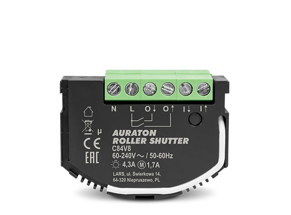
The AURATON Roller Shutter is used to control devices equipped with a rotary drive with the ability to change direction and with adjustable speed locks in the form of limit switches. In practice, these include roller shutters and gates. The device should be connected according to the diagram. Both single and double bi-stable and mono-stable switches are supported. Control involves activating a relay and transferring a phase to the appropriate motor input. It allows for programming movement times in a given direction after calibrating the device (Note: The motor must be equipped with limit switches).
The device measures receiver parameters such as active power and total energy consumption. The AURATON Roller Shutter is equipped with a LED indicating the current operating status and a button for adding or removing the device from the AURATON Smart system (Fig. 1). The AURATON Roller Shutter is intended for indoor use only, for installation in junction boxes.
Device diagram
Fig. 1.
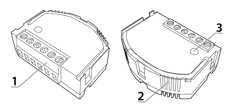
- Connection terminals
- Indicator diode
- Pairing/Removing Device from System Button
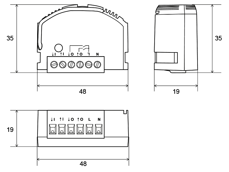
Device dimensions
Device functions
The device was designed and manufactured in Poland in accordance with applicable standards.
It is suitable for installation in junction boxes with a minimum depth of 60 mm and meeting national standards.
- control of the rotary motor in both directions,
- ability to control roller shutters and gates,
- Possibility of control using monostable, bistable or remote buttons,
- measurement of the supply voltage value,
- measurement of active power and total energy consumption by the connected receiver,
- secure radio connection using the AURA protocol.
- software protection against switching on the voltage when it is not within the permissible operating range of the device,
- software overcurrent protection protecting the module against damage,
- software protection against exceeding the permissible internal temperature,
- two-color internal LED to identify device status.
- Active power – the power consumed by a device, resulting from the supply voltage, current, and load characteristics. This value directly translates into electricity bills.
- Electricity consumption – a measure of electricity consumption, expressed in kWh (kilowatt-hours). This value is also displayed on the electricity meter installed in every home.
Connection to the power supply
The AURATON Roller Shutter may only be connected to a 230 V AC power supply. The electrical installation should be protected by a circuit breaker with a maximum current of 10 A, meeting national standards. The minimum cross-section of the connecting wires should be 1 mm², while the maximum cross-section of the connecting wires cannot exceed 2.5 mm². No additional settings are required for either type of supply voltage. The connection method is shown in the drawing below. Pay particular attention to the markings of the N and L power terminals.
Improper connection of the device may result in damage to the device and pose a risk of electric shock.
How to connect the power supply to the AURATON Roller Shutter module with roller blinds
Double connector
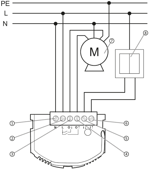
Alternating voltage 60-240 V AC:
Explanations for the diagram:
- (N) neutral terminal
- (L) phase wire terminal
- (O1) motor input – direction A
- (O2) motor input – direction B
- (l1) connector clamp – direction A
- (l2) connector clamp – direction B
- engine
- wall switch
Single connector

Alternating voltage 60-240 V AC:
Explanations for the diagram:
- (N) neutral terminal
- (L) phase wire terminal
- (O1) motor input – direction A
- (O2) motor input – direction B
- (l1) connector clamp – direction A
- (l2) connector clamp – direction B
- engine
- wall switch
Calibration of the AURATON Roller Shutter with actuator
Basic calibration
For the AURATON Roller Shutter to work properly with an actuator (e.g., a roller shutter), the controller must be calibrated. To initiate the calibration process, use the wall switch to perform the following sequence:
- Press and hold the connector button for 5 seconds.
- Release the switch button for 1 second.
- Press and hold the connector button for 5 seconds.
- Release the switch button for 1 second.
- Press and hold the connector button for 5 seconds.
After this step, the roller shutter will move to its extreme positions to perform calibration. A full movement in both directions is required, which usually means three passes, the first of which establishes the initial position.
Manual calibration of the 1% point
If we're controlling a device with an additional initial opening degree, we can include it in the first 1%, even if it represents a significant portion of the operation. In roller blinds, for example, this is the level at which the slats are straightened, leaving the window still covered but with a small clearance. Adding this level allows for better control of the remaining roller blind positions, both from the top and bottom. To set the 1% threshold, press any button on the switch during the calibration process when the device is in the position we want to define as 1%. The device will then perform an additional movement compared to the standard calibration. The button should be pressed during full movement in the given direction (2nd or 3rd pass; the 1st is ignored).
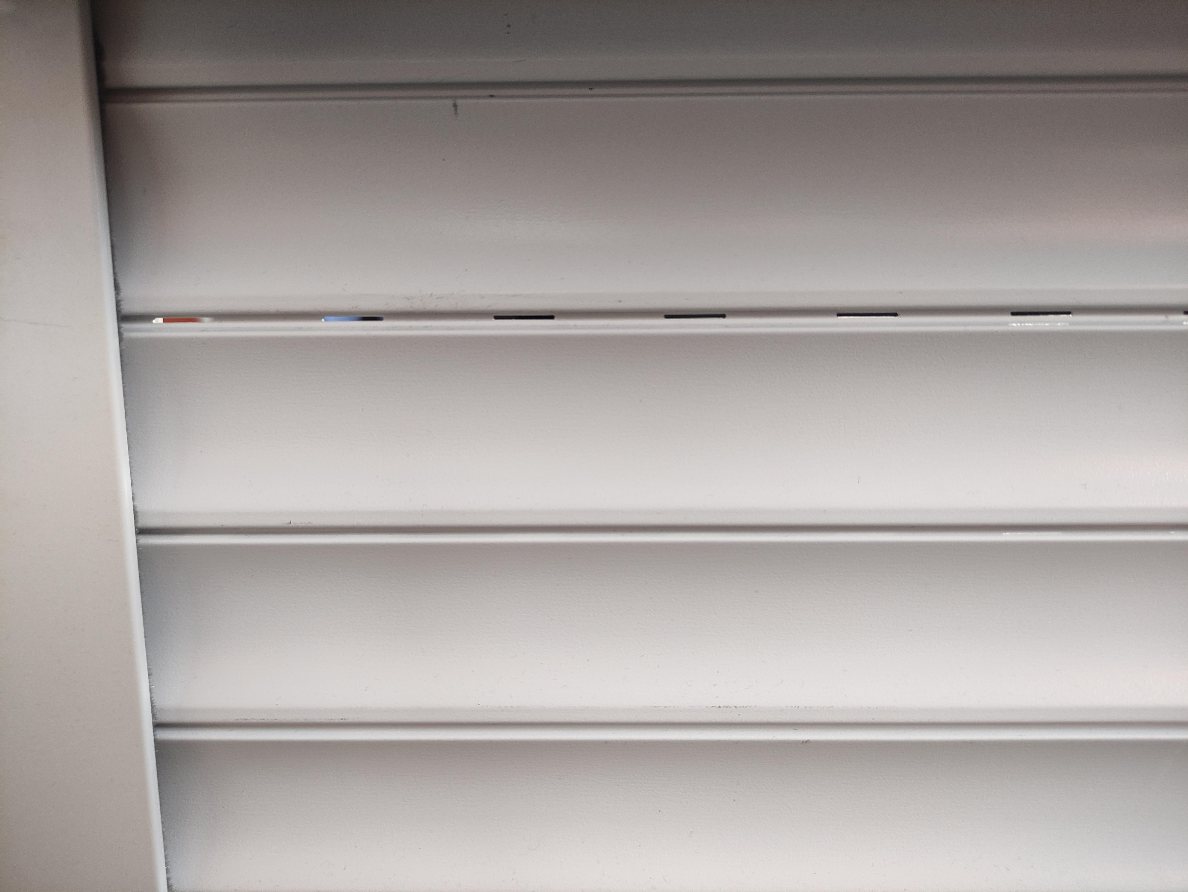
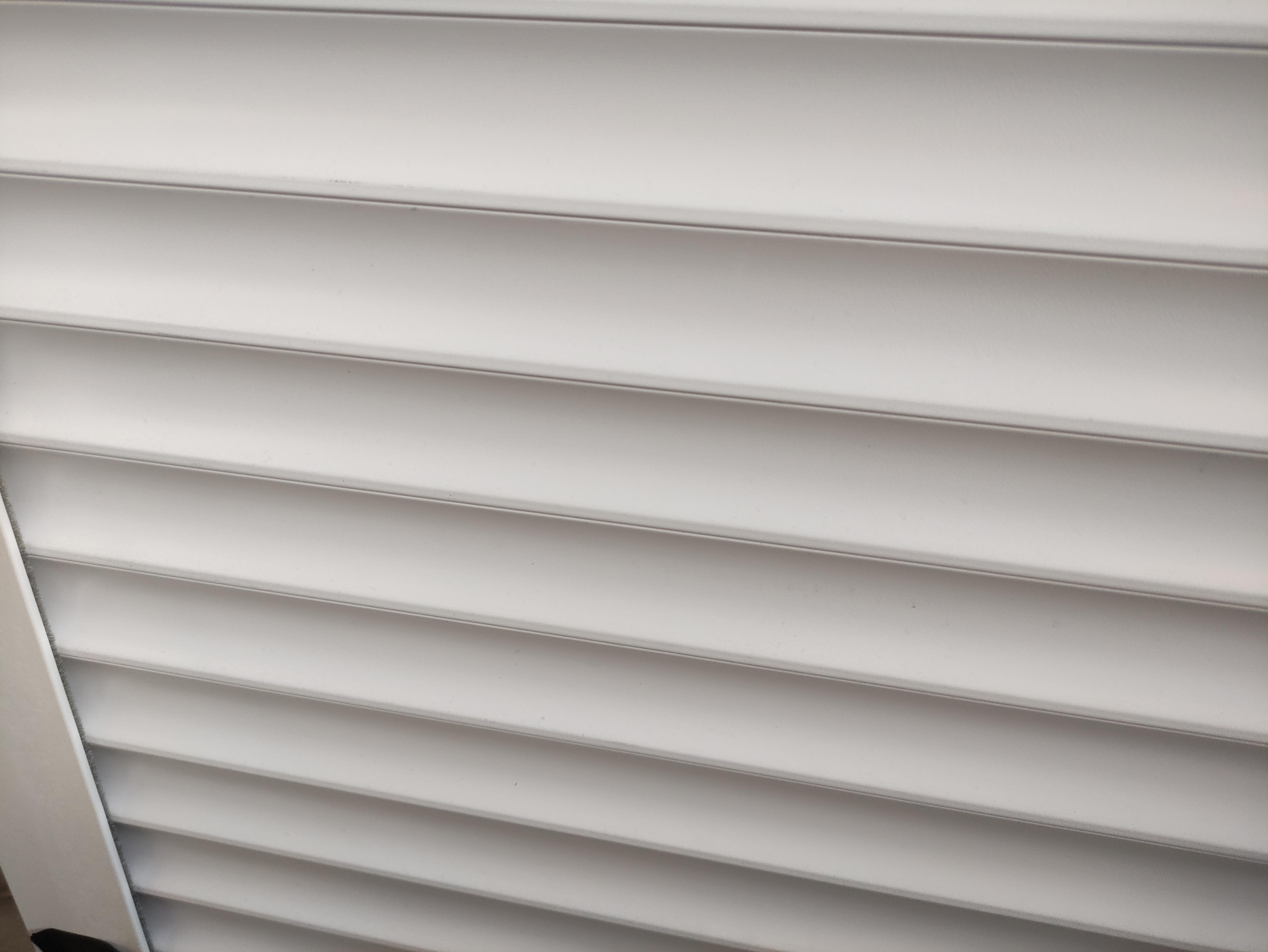
Fig. 4. Example of roller blind settings, on the left with a "clearance", on the right fully closed.
Device pairing
Once the module is properly connected and powered on, the LED inside the housing should begin flashing red, as shown in Fig. 5.1. This indicates that the device is not paired with the AURATON Smart system. If the LED flashes as shown in Fig. 5.3 or Fig. 5.4, the device must first be removed from the system.
Enabling pairing – AURATON Roller Shutter
To activate pairing, hold down the button on the device's housing. Release the button when the LED lights green. The pairing process should begin, and the LED should flash as shown in Figure 5.2. During this time (approx. 30 seconds), initiate pairing on the other device you want to pair with the AURATON Roller Shutter.
Enabling pairing – AURATON Pulse control panel
Pairing in AURATON Pulse is enabled using the AURATON Smart App. On the next screen, name the device you're adding. After entering the name, press the "Add" button. Once successfully paired, you can place the device in any previously added room and add it to your favorites.
Fig. 5. Adding a device to the AURATON Pulse control panel
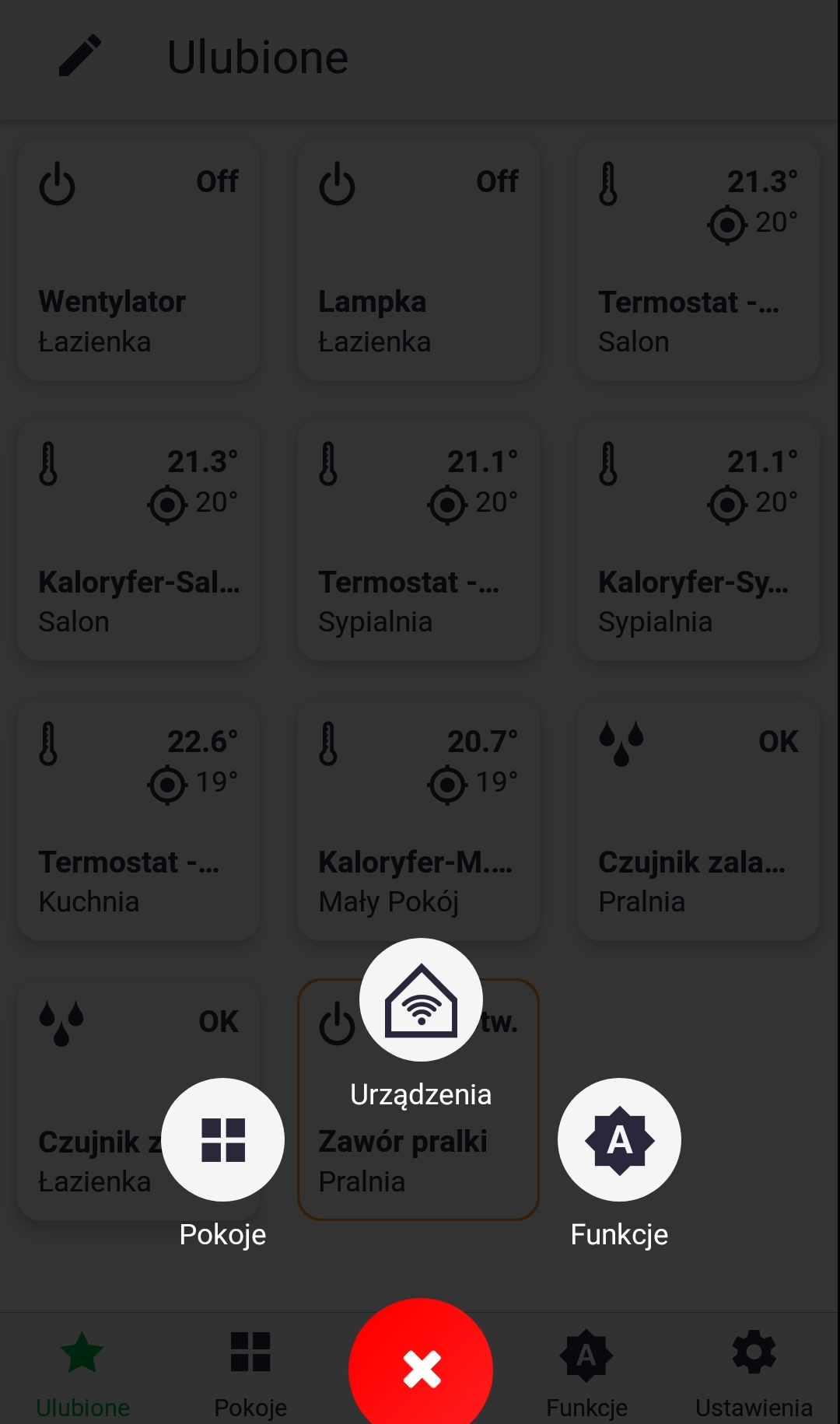
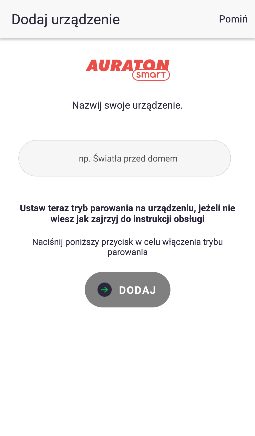
Fig. 6. Time graphs defining how the LED lights up when the device is paired:
- Condition: The device is not connected to the system.
Diode: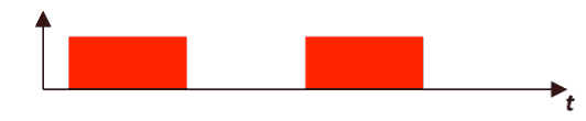
- Condition: Device in pairing mode
Diode: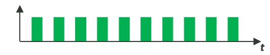
- Condition: The device is connected to the system and is working properly.
Diode: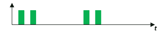
- Condition: The device cannot connect to the AURATON system – check the range.
Diode: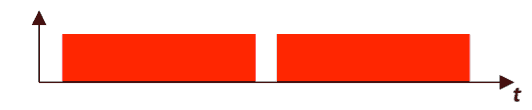
Factory reset
To restore the factory settings, hold the button during normal operation (approx. 5 seconds) until the LED lights red. Release the button and press it again within 3 seconds to confirm the operation. All information on the device will be cleared. The LED should indicate that it is not connected to other AURATON Smart system devices (Fig. 5.1).
Control
Local control
The AURATON Roller Shutter can be controlled locally using a single or double monostable or bistable switch. The difference in control between monostable and bistable switches results from their design. Bistable switches retain their state after clicking, while monostable switches, also known as bell switches, activate a phase only for a short period.
Single switch – monostable
Direction control is alternating. A single click initiates movement, another click stops, and another click reverses direction. The moment the final position is reached, the movement is stopped.
Example of subsequent "presses" of the connector:(switch clicked)

(link clicked)
(switch clicked)
(terminal moment)
(click)
Single switch – bistable
Similar to controlling a monostable switch, the direction of action is controlled alternately. A "click" causes movement, an "unclick" stops, and another "click" causes movement in the opposite direction. The moment the end position is reached is equivalent to a stop, but to restart the motor, the switch must be "unclicked" and "clicked" again.
Example of subsequent "presses" of the connector:(switch pressed)
(switch in neutral position)
(switch pressed)
(end position, switch pressed)
(end position, switch in neutral position)
(switch pressed)
Double switch – monostable
Control is controlled by the clicked switch key. Clicking the "A key" initiates movement in the "A" direction, and the "B key" initiates movement in the "B" direction. Pressing any key during movement stops the motor.
Example of subsequent "presses" of the connector:(connector A)
(connector A or B)
(connector B)
(terminal moment)
(connector A)
Double switch – bistable
Control is controlled by pressing the switch button. Clicking "key A" initiates movement in direction "A," while "key B" initiates movement in direction "B." Stopping is accomplished by "unclicking" the button that is "pressed." It is recommended to use a switch designed for roller shutters, with the ability to be locked in both directions simultaneously. Failure to follow this recommendation will not cause damage, but pressing it simultaneously will operate as with a "single bistable switch."
Example of subsequent "presses" of the connector:(connector A)
(connector A)
(connector B)
(terminal moment)
(connector A)
Control via the AURATON Smart application
Using the AURATON Smart application, it is possible to control the opening/closing level of the roller shutters after prior calibration.
Fig. 7. Entering the electricity tariff:
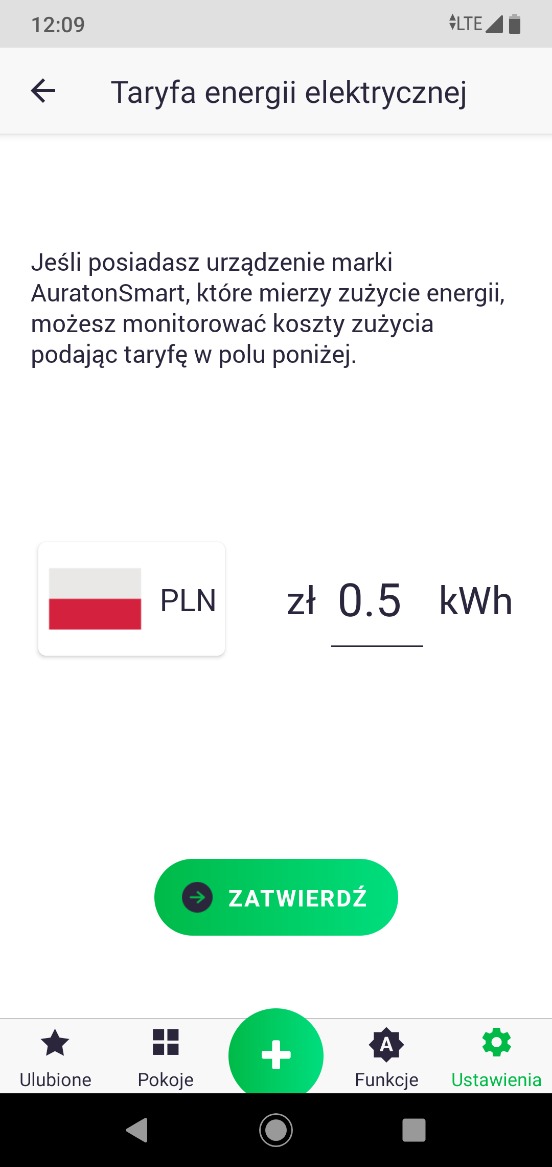
Fig. 8. Controlling a device connected to the AURATON Smart system:
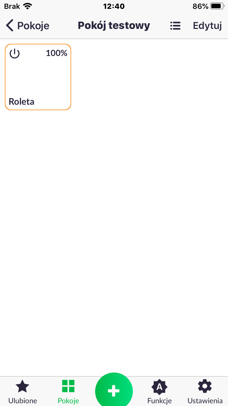
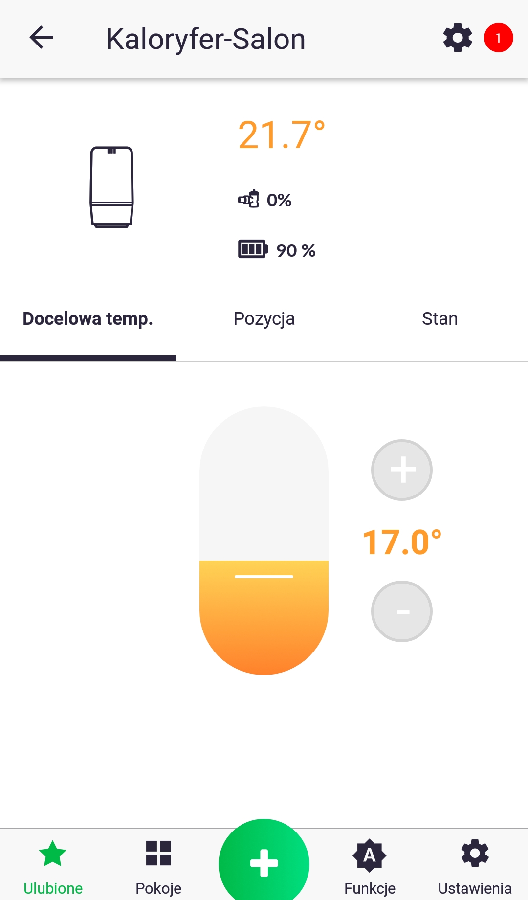
Device Tile
After adding the AURATON Roller Shutter device and assigning it to the appropriate room, you should see a tile for your device. It shows its current position as a percentage. Clicking on it allows you to control full opening/closing. Each subsequent click changes the direction.
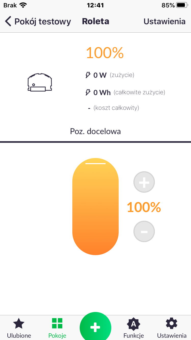
Internal menu (1)
Holding down the tile will reveal the device's internal menu. It includes the current blind position, information about current and total energy consumption, and a slider for setting the target position.
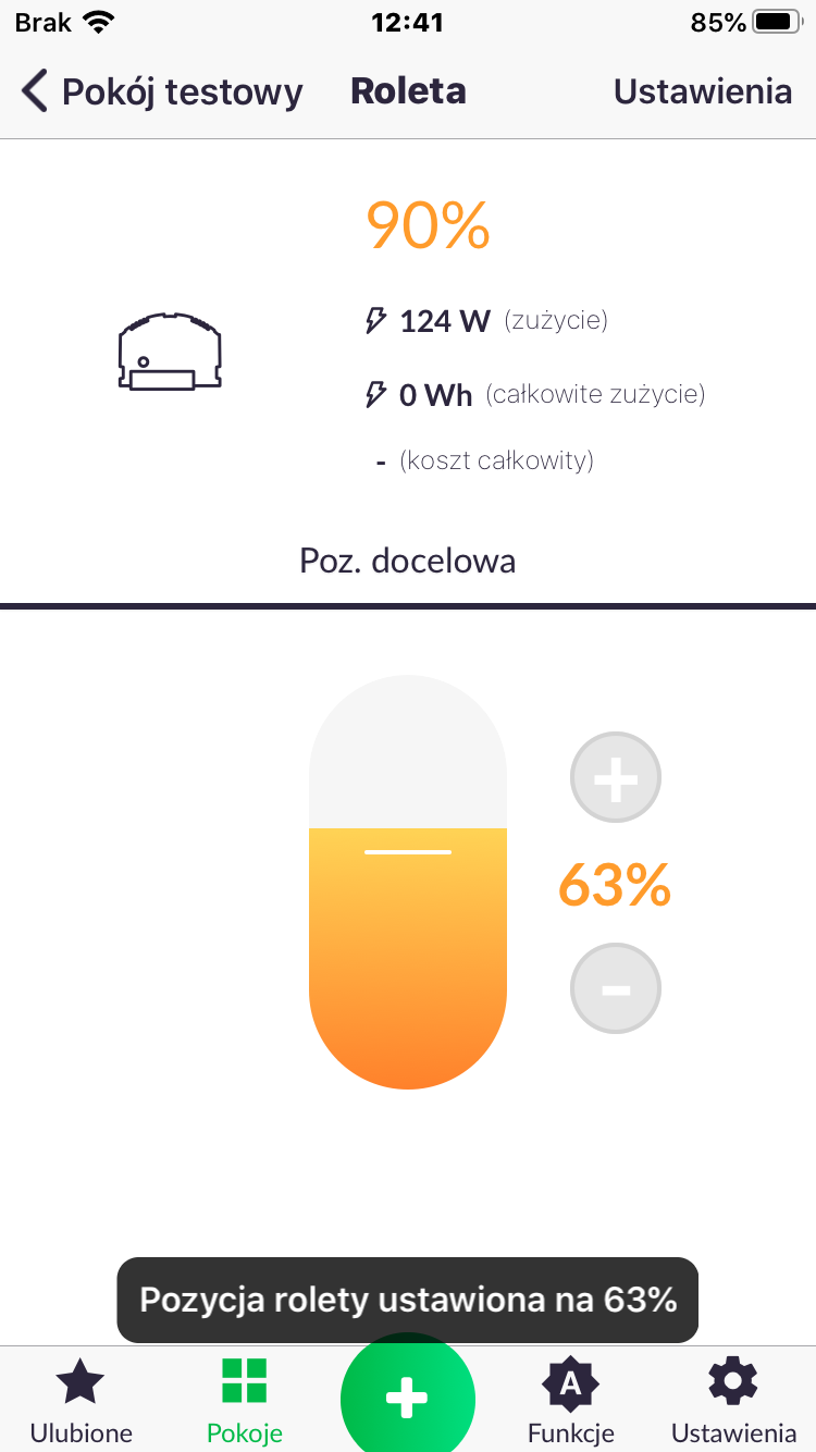
Internal menu (2)
Once the slider is moved to the selected level, the device begins to move in the appropriate direction. A value should appear in the current energy consumption field if the device is in motion.
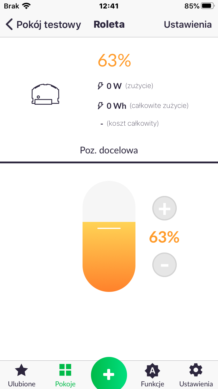
Internal menu (3)
When the current position matches the target position, the device stops. Current power consumption should be 0 W.
Peripheral software update
The AURATON Smart system allows for remote software updates for peripheral devices. Updates are performed over the air (OTA), which is always followed by a device restart. If, after installing the new software, the device is enriched with features you don't like, you can manually restore the previous software version.
Fig. 9 Subsequent stages of software update.
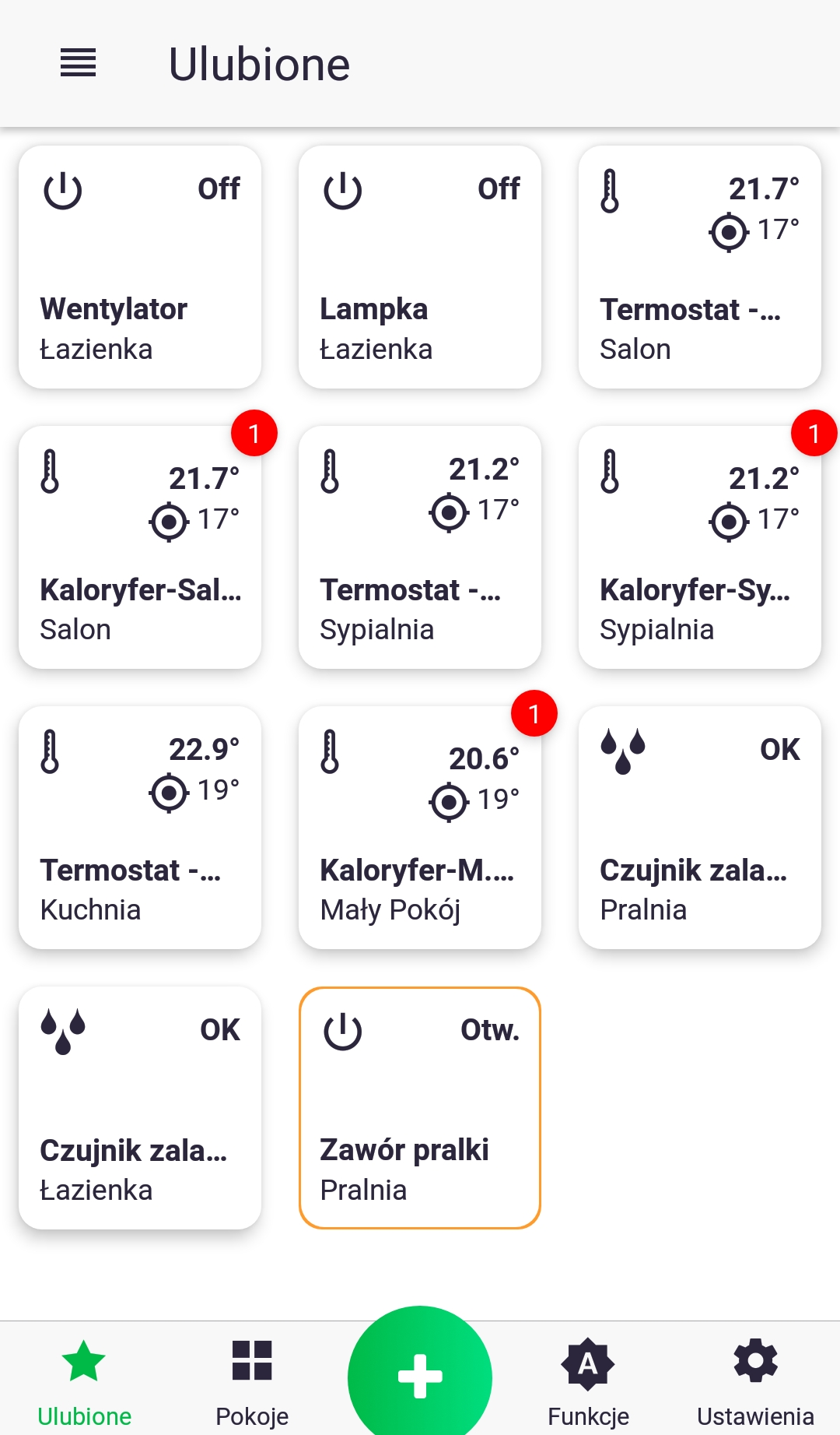
- A red checkmark indicates that an update is pending for the device. To perform the update, long-press the icon to access the control screen.
- Follow the marker and click the device settings icon. On the next screen, press "Software Update."
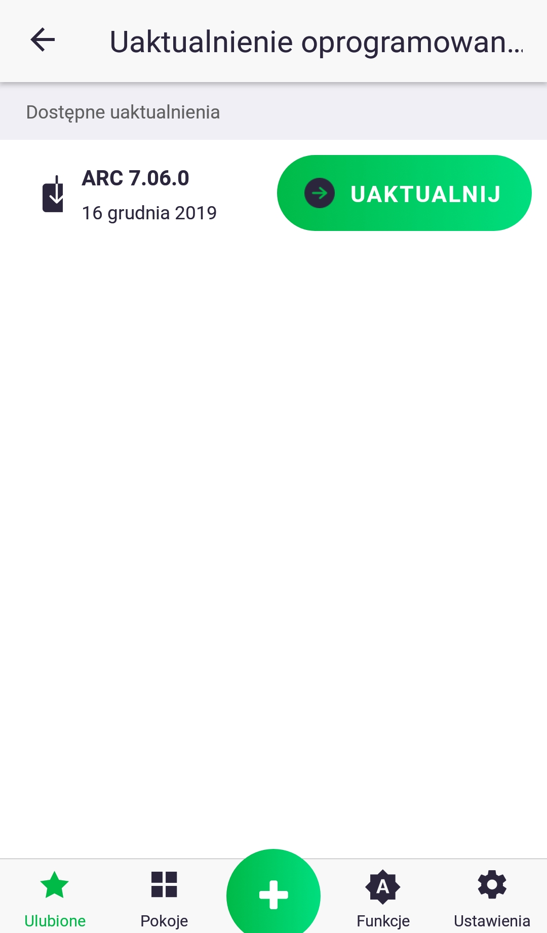
- Click "Update." The update may take several minutes, during which the AURATON Pulse control panel will not respond to commands issued from the app. After the update, the red check mark should disappear; if it doesn't, repeat the steps.
While downloading the software update, the internal LED should flash as shown in Figure 9.1. After downloading the update, the new software can be uploaded to the device (Figure 9.3) or rejected in case of an error (Figure 9.4). After the update, and before the device restarts, the LED will flash as shown in Figures 9.5-9.6 depending on the success of the update.
Fig. 10. Time graphs defining the LED lighting pattern during software update:
- Condition: Device in OTA update mode.
Diode: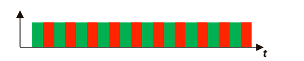
- Condition: Restoring a previous version of the software.
Diode: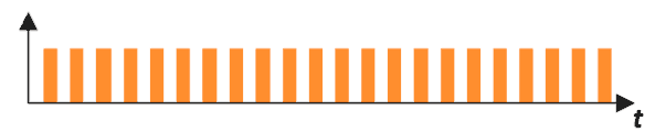
- Condition: Uploading software
(continuous diode status until upload is completed)
Diode: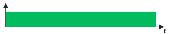
- Condition: No software to load (2 blinks).
Diode: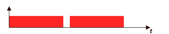
- Condition: Software loaded correctly (3 flashes).
Diode: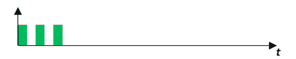
- Condition: Software failed to load, incorrect version in memory or memory communication problem (3 flashes).
Diode: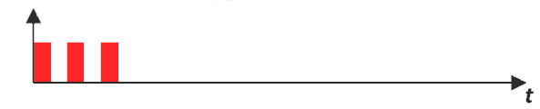
- Condition: An unexpected error occurred during a software update, which prevents the device from turning on correctly.
Contact with service required.
Diode: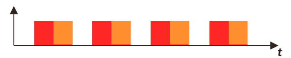
Restoring a previous software version
After completing the update, or if it fails (Fig. 9.4), you can roll back to the previous software version. There are two ways to do this.
With power disconnection
After pressing the button on the device's housing, turn on the power – the LED will flash as shown in Fig. 9.2. While still holding the button, wait until the LED stops flashing. The next steps are the same as for updating the software.
Without disconnecting the power supply
If the device starts correctly and responds to the button according to basic functions, such as pairing and deletion, you can restore the previous version without unplugging the device. Hold the button for at least 7 seconds until the LED turns orange, then release it. Then, while the LED remains lit, hold the button again and proceed as in the example with disconnecting the power supply.
Technical data
| AC supply voltage: | 60-240V AC, 50-60Hz |
| Maximum power consumption: | ≤1 W |
| Power consumption in standby mode: | ≤0.4 W |
| Operating temperature: | 0-35 °C |
| Power cable type, maximum permissible power cable cross-section: | 3 x 2.5 mm2 |
| Permissible load: | up to 4.3 A (<1 kW) |
| Security type: | An external circuit breaker with a maximum current of 10 A is required. |
| Control element: | Electromagnetic relay with micro-break |
| Control method: | remotely – by radio, locally – using buttons |
| Maximum number of paired devices: | 1 |
| Cooperation with the Internet headquarters | AURATON Pulse |
| Reception: | up to 50 m in open space up to 30 m in a building, depending on obstacles |
| Radio frequency: | 868.150 MHz 868.450 MHz |
| Radio signal strength: | up to 11 dBm |
| Radio receiver category: | 2 |
| Radio protocol: | AURA |
| Degree of protection: | IP20 |
| Dimensions [mm]: | 48 x 35 x 19 |
Disposal of the device
O
Devices are marked with a crossed-out waste bin symbol. In accordance with European Directive 2012/19/EU and the Waste Electrical and Electronic Equipment Act, this marking indicates that this equipment, after its useful life, must not be disposed of with other household waste.
Users are obligated to dispose of it at a collection point for used electrical and electronic equipment.
LARS Andrzej Szymański hereby declares that the AURATON Roller Shutter radio equipment type is in compliance with Directives 2014/53/EU and 2011/65/EU. The full text of the EU declaration of conformity is available in the download section below.
Manufacturer's address and contact details:
LARS, ul. Świerkowa 14
64-320 Niepruszewo
www.auraton.pl